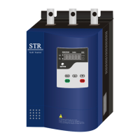
Appendix 5: A Series Typical Wiring Diagram Appendix 5: A Series Typical Wiring Diagram
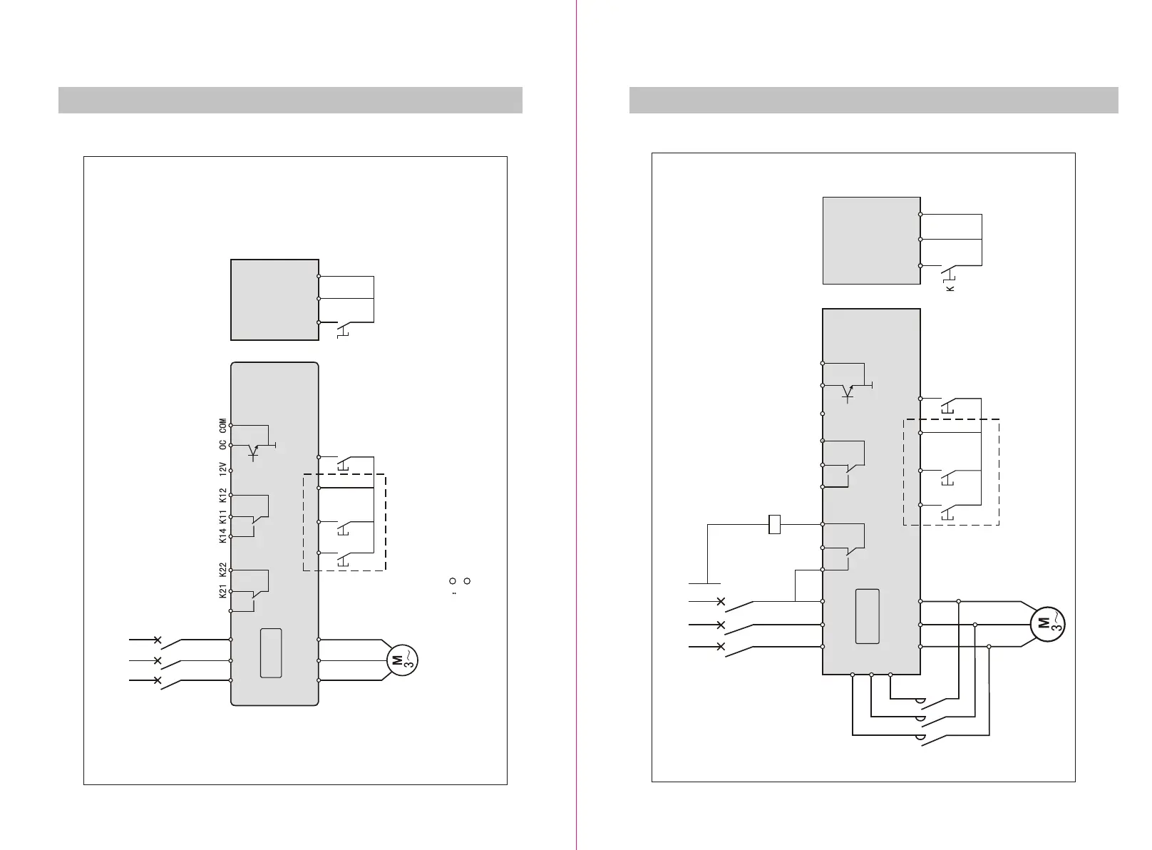
Appendix 6: B SERIE typical wiring diagram Appendix 6: B SERIE typical wiring diagram
38
OPERATION
MENU
39
OPERATION
MENU
Figure F-5 Figure F-6
L1 L2 L3
QF
K24
R S T
U V W RUN
STOP COM JOG
STR(A)
BypassBypass FaultFault
Start FinishStart Finish
Three lineThree line
RUN
STOP COM
K
Note There are inner bypass contactor in A series product, so there are not terminals U1,V1,W1.Note There are inner bypass contactor in A series product, so there are not terminals U1,V1,W1.
There are two control mode: 2-line, 3-line. Start when K is close. Stop when K is open. There are two control mode: 2-line, 3-line. Start when K is close. Stop when K is open.
Two lineTwo line
L1 L2 L3
QF
N
K21 K22 K14 K11 K12 12V OC COMK24
KM
RUN
STOP COM JOG
STR(B)
R S T
U V W
U1
V1
W1
RUN
STOP COM
KM
Three lineThree line
Two lineTwo line
BypassBypass FaultFault
Start FinishStart Finish
 Loading...