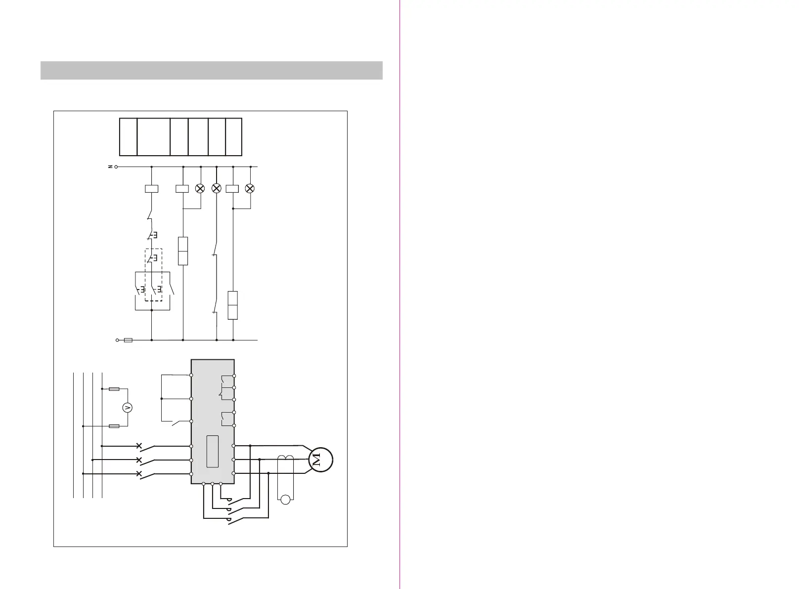
Appendix 7: G SERIE typical wiring diagram Appendix 7: G SERIE typical wiring diagram
40
OPERATION
MENU
Figure F-7
STR(B)
L1
L2
L3
N
QF1
FU1
R
PV
R S T
U V W
U1
V1
W1
COM
RUN
STOP
KM
PA
A
LH
U V W
FU3
AR
AC220V
SB1
KA1
SB2
KA1
KM
HG
HR
HY
KMKA1
FUSEFUSE
START/
STOP
START/
STOP
BYPASSBYPASS
RUNNING RUNNING
STOPSTOP
FAULTFAULT
FU2
KA1
K22 K24 K11K12K14
K22 K24
STRB
AR
STRB
K12 K14
3~
BypassBypass FaultFault
Main circuitMain circuit
Control circuitControl circuit
Note:This circuit diagram is designed for the
the motor which power is 90KW or above.
Note:This circuit diagram is designed for the
the motor which power is 90KW or above.
 Loading...