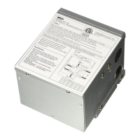
Wiring Instructions
For 20A applications, use 12AWG copper conductors only. For 15A applications, use 14AWG
copper conductors only. All wiring shall meet local codes/standards and be performed by
qualied personnel.
• If the remote panel is NOT used or NOT available, the priority circuit shall be connected
to circuit A.
• Remove the lid and put it in a temporary safe place.
• Feed Romex cable from the 15A (for EM-15) or 20A (for EM-20) circuit breaker into the
centrally-located cable clamp.
o Connect Black wire to TB1 (AC Input / Line).
o Connect White wire to TB4 (Neutral).
o Connect Ground wire to TB7 (FG).
o Fasten all terminals down (suggested torque 7 in-lbs).
o Secure the AC Power wire with the two-screw clamp connector.
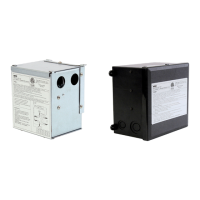
• Feed 2 Romex cables from the Circuit A and Circuit B into the cable clamp near the end.
o Connect the Circuit A Black wire to TB2 (Circuit A).
o Connect the Circuit A White wire to TB5 (Neutral).
o Connect the Circuit A Ground wire to TB8 (FG).
o Connect the Circuit B Black wire to TB3 (Circuit B).
o Connect the Circuit B White wire to TB6 (Neutral).
o Connect the Circuit B Ground wire to TB9 (FG)
o Fasten all terminals down (suggested torque 7 in-lbs).
o Secure the wires for Circuit A and Circuit B in the two-screw clamp connector.
• Put lid back on the EM-15 / EM-20.
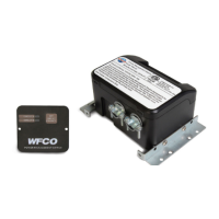
• For the Remote: Mount the Remote Control in a convenient location. Route and connect
the remote cable into the 6-pin phone connector on both the EM-20 and the remote.
Air Conditioner Logic Wiring for the EM-20
is section shall be used if you have two air conditioners designed to be used with an energy
management system. For best operation, make sure the air conditioner fan is set to auto.
EM-20 Molex
5569 Pin #
EM-20 Molex 5569
Wire Color
Description Air Conditioner
Connections
1 BLK AC1-NC
2 WHT AC1-COM AC1-Load Shed
3 BLU AC1-NO AC1-Load Shed
4 RED AC2-NC
5 ORG AC2-COM AC2-Load Shed
6 YEL AC2-NO AC2-Load Shed
e EM-20 logic relays provide dry relay contacts and operate as follows: Under normal
operation with both circuits ON, the logic relays will be de-energized (relay common
connected to the normally closed contacts). When the total current exceeds the upper trip
limit, the logic relay for the secondary channel is energized (relay common connected to the
normally open contacts).
12