SIGNAL INPUT CONNECTIONS
Do not place the subwoofer close to surfaces or objects that may
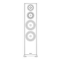
The PPS 1A Active Sub Bass Unit
rattle. The floor under the subwoofer should be sound.
There are two alternative connections.
The PPS1A sub bass unit is intended for use with the matching
PPS 1 panels and must not be used with other satellites.
On the rear of the sub bass unit there is a pair of RCA phono
plugs. These are the preferred connections and should be used
REAR CONNECTION PANEL
Check that all system connections are correct. Set the Master
to connect the unit to regular Audio separates (see the drawing
Level Control on the sub bass unit to minimum and the Power
below). The upper, Red socket connects to the Right Channel
switch to OFF. Connect the power lead to the mains.
and the lower, Black socket connects to the Left channel.
Switch on the power to the subwoofer and check that the
On the front panel there is a Stereo 3.5mm jack socket. This
Standby Indicator on the front panel glows. Connect the power
may be used for connecting the to the headphone output of a
to the rest of the system. The system is now operational.
portable audio product, or possibly a computer sound card.
BASS LEVEL CONTROL
Never connect the loudspeaker outputs of an amplifier direct to
The Level control is located on the front panel. Use this control to
the signal inputs of the sub bas unit. If you are usinga computer
alter the amount of bass the subwoofer puts out. Do not set too
sound card make sure you connect the LINE outputs only.
high a level or the sound will be bass heavy and the system may
NOTE :Only one input may be connected at any time.
distort at high volumes.
CONNECTING THE PANELS
MASTER LEVEL CONTROL
Connect the Left Panel Speaker terminals on the sub bass unit to
This control alters the overall volume level of the loudspeaker
the Left panel. Press the lever at the side of the terminal and
system. It may be used in two ways.
insert the cable. Release the lever and the wire is held firm.
Where the Source Unit has a fixed output level: Use the
Connect the Red (+) speaker terminal on the panel to the Red
FRONT PANEL
Master Level as the main volume control for the system. This is
(+) terminal on the sub bass unit. Connect the Black (-)
typically be the case if you were using a Tuner. Some CD Players
speaker terminal on the panel to the Black (-) terminal on the
and Cassette players have variable line outputs, most don’t.
sub bass unit. Connect the Right Panel in the same way
Where the Source Unit has a variable output level: This is
Terminals should always grip the bare wire and no strands
typically be the case if you are using the unit with a computer
should ever touch adjacent terminals.
sound card or via the Headphone socket on a portable audio
Positioning The Sub Bass Unit
player. In this case you may either use the Master Level control
as the main system Volume control or as a preset.
Although the unit may be placed almost anywhere in the room,
POWER CONNECTIONS
even behind the sofa or the TV set, we recommend that it be
Using the Master Level ae a Preset Control: Set the control
This unit is set to the mains voltage marked on the amplifier
placed in front of the listener and central to the listening
so that there is a wide range of operation at the source unit and
panel. Before connecting check that this voltage is correct for
position. There should be a mains outlet within easy reach.
that the level is not “squashed up” at either extreme. (This will
your mains supply.
normally correspond tothe 2 O'clock position). The main volume
230 volt units: 220 - 240 VAC 115 volt units: 110 - 120VAC
control on the computer or portable unit will now be used as the
If you move to an area with a different mains supply consult
system control.
your Wharfedale dealer to arrange conversion of this product.
Auto Power On
Unwrap the supplied connecting cord and plug it in to the Power
We suggest you position the subwoofer about 20cm from the
The sub bass unit remains in Standby when there is no signal.
Input socket on the sub bass unit. Do not connect the unit to the
wall. Placing the unit close to the wall will enhance the bass;
When it detects a signal it will switch on and the Operation light
mains power or switch the power on at the mains or the sub
placing it across the corner of the room will increase the bass
glows. If there is no signal for about 30 seconds it will go to
bass unit at this time. (Always
further, possibly at the expense of clarity. Experiment with a
Standby and the Standby light will again glow.
variety of locations and sources before making a final decision.
Allow least 450mm between the subwoofer and the TV or the
colours on the screen may be disturbed. To restore normal
colour, switch off the TV set and subwoofer and move the
subwoofer away. Switch on again after 15 minutes.
unplug the sub bass unit if it is
not going to be used for long periods.)
Initial Setting-up And Operation
The PPS 1 is not supplied with fastenings. You will need four
Introduction
No.8 Round Head screws and fixings appropriate to the
The Wharfedale PPS 1 Active system consists of a powered sub
structure and material they are to be applied to. Seek qualified
bass unit with two satellite panels based on revolutionary
assistance if necessary. The mounting screws must be securely
NXT™ Surface Sound technology. This unique technology
fastened into the wall or base structure.
enables all listeners in the room to enjoy spacious, detailed
sound, not just the favoured few directly on line with the
The assembly should be capable of taking the weight of the
speakers.
panels, plus any pulling force to which they might be subjected.
Please read all the safety information before installing your PPS
1 Active System. It will help you install your system correctly.
DO NOT connect loudspeaker terminals to the mains supply.
Ensure that all loudspeakers in the system are correctly wired
and are in phase.
Site the LP 1 A sub bass unit at least 0.5m from TV sets and
magnetic storage media. The PPS1 panels may be safely used
close to a TV set.
Unpacking
Unpack your system with care. Be careful not to damage the
panels and active bass unit cabinet when removing the
polythene sleeves. Check each speaker and in the event of any
transit damage, immediately contact your Wharfedale dealer.
Retain the packaging for future transit.
Compatibility
Your Wharfedale PPS 1A system has been designed to be
If you have any doubts concerning your particular circumstance
s your dealer will be happy to advise.
The PPS1 panels employ a protection mechanism that mutes
the sound if the power input is too great. If the output is muted,
turn down the main volume control on the system for a few
seconds to reset the level.
Your PPS 1 panels are supplied fitted with lightweight decor
pictures fixed to the panel surface with low-tack adhesive. If you
wish to remove or change these pictures, please read the
section 'Customising the PPS 1 Panels'
Mounting the Panels
The PPS 1 panels are designed to wall mount. Conventional
loudspeakers need to be focussed on the listening position and
placed at an equal distance from the listener. Although this
conventional placement is still the preferred position, the
position of the panels is not critical, except that you should not
position the panels immediately next to each other. The panels
can be placed at different heights to each other and at different
distances from the listening seat.
Each PPS 1 panel should be placed to the front or side of the
listening position.
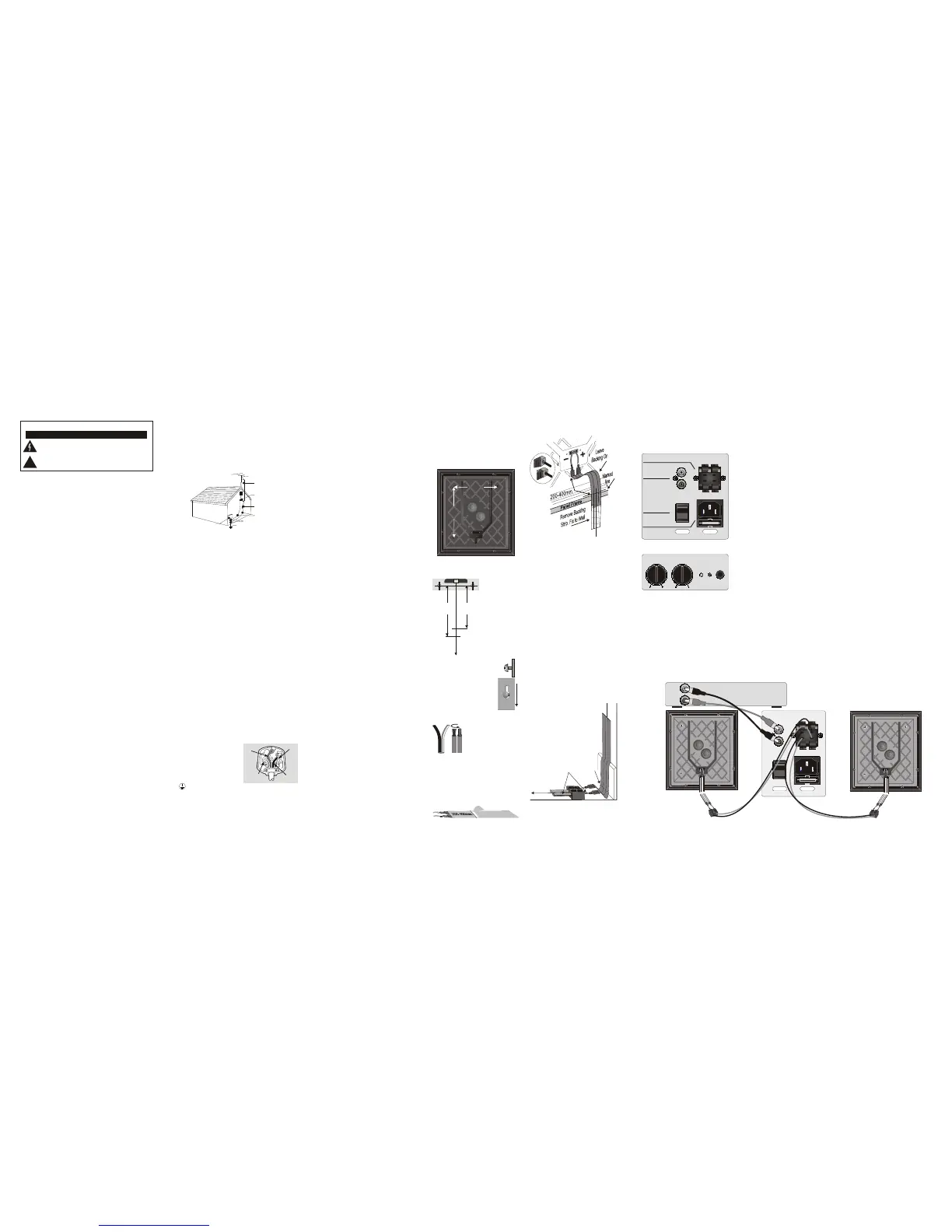
Fixing the Panels to the Wall
Three keyhole slots are located on the back of each panel so that
the panel may be wall mounted in either portrait or landscape
mode.
used
in conjunction with a computer, the headphone output on a
portable audio unit, or to f a CD player or other Hi Fi uni that has
a line output. The PPS 1A system can also be connected to a
preamplifier output , or to a spare recording output of a regular
Hi Fi system, to extend the sound to a remote location.
DO NOT connect the loudspeaker outputs of any unit to the
audio inputs of the 2.1.
The subwoofer has three amplifiers, one for the sub bass unit
and an amplifier for each NXT panel. The deep bass goes to the
subwoofer and the rest of the audio signal to the panels.
282mm
327mm
Preparing Cables
Determine the location of each panel and if it is to be mounted
portrait or landscape.
Mark out the mounting
centres.
282mm(Portrait)
327mm(Landscape)
Now mark a vertical centre
line down to the floor.
Mark another short line on
the wall at the position
shown. This line is the
upper level for fixing the
cable to the wall.
Drill and fix a No. 8 screw and suitable
wall plug. The screw should protrude
about 5mm from the wall.
Align the keyhole slots over the screws.
Pull gently downwards to secure the
panel. When both panels are correctly
sited, lift them off and lay them to one
side ready for connecting.
Suitable loudspeaker cable is
supplied to connect the pnels to the
subwoofer. This has a tracer on
one cable to aid identification
Divide the cable into two lengths.
cable
.
Prepare each by splitting the twin cores to a depth of
about 25mm . Strip about
length
at each end 7mm of insulation from
each wire. Lightly twist the strands to gather the ends.
Two 2 metre lengths of self adhesive flat cable are supplied to
help you cable the PPS 1 panels. Take each flat cable and mark
on the back a line 200 mm (400mm landscape) from one end.
Carefully score through the backing tape and peel away a short
length of backing tape
To Floor
420mm
Portrait
370mm
Landscape
Connecting the PPS 1 Panels
The PPS 1 panel uses spring terminals located on the rear.
Positive, Red(+) and Negative, Black(-) terminals are clearly
identified.
The flat cables terminate in wire pigtails. Take each flat cable
and connect it to a PPS 1 panel at the end you have prepared.
Connect the pigtail with the Black sleeve to the Black terminal on
the PPS1 panel. Press the lever at the side of the terminal and
insert the cable. Release the lever and the wire is held firm. Now
connect the pigtail with the Red Sleeve to the Red terminal.
Terminals should always grip the bare wire and no strands
should ever touch adjacent terminals.
Hang each panel and cable assembly securely on the wall via the
mounting slots. Hinge the panel slightly away from the wall and
place the cable against the wall with the start of the exposed
adhesive against the marked horizontal line. Ensure that the
pigtail with the BLACK sleeve is to the RIGHT as viewed from the
front.
Run the cable carefully down the wall, peeling off the backing
tape and attaching the cable as you go. Keep the cable centered
on the vertical line.
When the cable is 5mm above the floor covering, cut away the
loose backing strip and run a cloth over the cable to press it
firmly to the wall.
The flat cable is connected to the LP 1 sub bass unit via a length
of speaker cable attached to the flat cable with a twin terminal
block.
Partially unscrew the screws on the terminal
block. Insert a bared end of each pigtail on
the flat cable into each hole at one end of the
block and screw them in place. Now screw in a
prepared speaker cable at the other end.
Make sure that the stripe or rib on the speaker
cable connects to the BLACK pigtail.
The panels are now ready for connection to the sub bass unit.
Connect striped
core to pigtail with
black marker
Lower limit
of adhesive
To Sub-Bass Unit
Wharfedale PPS 1 System User Guide
NXT™ is a trademark of New Transducers Ltd.
AC INPUT
OFF
INPUT
ON
PANEL SPEAKER
+
_
+
_
RIGHT
LEFT
POWER
LEFT
RIGHT
Connections to Panels
Signal Input
Mains Power Input
Power Switch
MIN MAX MIN MAX
INPUT
STEREO
BASS
LEVEL
POWER
MASTER
LEVEL
RIGHT
SPEAKER
PANEL
AC INPUT
OFF
INPUT
ON
PANEL SPEAKER
+
_
+
_
RIGHT
LEFT
POWER
LEFT
RIGHT
LEFT
SPEAKER
PANEL
RIGHT
LEFT
CD PLAYER, ETC
LINE OUTPUTS
LP 1A SUB BASS
TERMINALS
SYSTEM CONNECTIONS
Important Safety Precautions - Please Read Carefully!
Preliminaries
Antenna Grounding: If an outside antenna or cable system is connected to the product, be sure the antenna or
cable system is grounded so as to provide some protection against voltage surges and built-up static charges.
Article 810 of the National Electrical Code, ANSI/NFPA 70, provides information with regard to proper
grounding of the mast and supporting structure, grounding of the lead-in wire to an antenna discharge unit,
size of grounding conductors, location of antenna-discharge unit, connection to grounding electrodes, and
requirements for the grounding electrode. (Refer to diagram)
Power Lines: An outside antenna system should not be located in the vicinity of overhead power lines or other
electric light or power circuits, or where it can fall into such power lines or circuits. When installing an outside
antenna system, extreme care should be taken to keep from touching such power lines or circuits as contact with
them might be fatal.
Read Instructions: All the safety and operating instructions should be read before the product is operated.
Retain Instructions: The safety and operating instructions should be retained for future reference.
Heed Warnings: All warnings on the product and in the operating instructions should be adhered to.
Follow Instructions: All operating and use instructions should be followed.
Cleaning: Unplug this product from the wall outlet before cleaning. Do not use liquid cleaners or aerosol
cleaners. Use a damp cloth for cleaning.
Attachments: Do not use attachments not recommended by the product manufacturer as they may cause
hazards.
Water and Moisture: Do not use this product near water - for example, near a bath tub, wash bowl, kitchen
sink, or laundry tub, in a wet basement; or near a swimming pool; and the like.
Accessories: Do not place this product on an unstable cart, stand, tripod, bracket, or table. The product may fall,
Overloading: Do not overload wall outlets, extension cords, or integral convenience receptacles as this can
causing serious injury to a child or adult, and serious damage to the product. Use only with a cart, stand, tripod,
result in a risk of fire or electric shock.
bracket or table recommended by the manufacturer, or sold with the product. Any mounting of the product should
follow the manufacturer's instructions, and should use a mounting accessory recommended by the manufacturer.
Object and Liquid Entry: Never push objects of any kind into this product through openings as they may touch
dangerous voltage points or short-out parts that could result in a fire or electric shock.
Moving the Product: A product and cart combination should be moved with care. Quick stops, excessive force,
and uneven surfaces may cause the product and cart combination to overturn.
Heat: The product should be situated away from heat sources such as radiators, heat registers, stoves, or other
products (including amplifiers) that produce heat.
Ventilation: Slots and openings in the cabinet are provided for ventilation and to ensure reliable operation of
the product and to protect it from overheating, and these openings must not be blocked or covered. The
Servicing: Do not attempt to service this product yourself as opening or removing covers may expose you to
openings should never be blocked by placing the product on a bed, sofa, rug, or other similar surface. This
dangerous voltage or other hazards. Refer all servicing to qualified service personnel.
product should not be placed in a built-in installation such as a bookcase or rack unless proper ventilation is
Damage Requiring Service: Unplug this product from the wall outlet and refer servicing to qualified service
provided or the manufacturer's instructions have been adhered to.
personnel under the following conditions:
Power Supply Cords: Power supply cords should be routed so that they are not likely to be walked on or pinched
a) When the power supply-cord or plug is damaged
by items placed upon or against them, paying particular attention to cords at plugs, convenience receptacles,
b) If liquid has been spilled, or objects have fallen into the product
and the point where they exit from the product.
c) If the product has been exposed to rain or water.
Power Sources: This product should be operated only from the type of power source indicated on the marking
d) If the product does not operate normally by following the operating instructions. Adjust only those controls that
label. If you are not sure of the type of power supply to your home, consult your product dealer or local power
are covered by the operating instructions as an improper adjustment of other controls may result in damage and
company. For products intended to operate from battery power, or other sources, refer to the operating
will often require extensive work by a qualified technician to restore the product to its normal operation.
instructions.
e) If the product has been dropped or damaged in any way.
Polarisation: This product is equipped with a polarized alternating-current line plug (a plug having one blade
f) When the product exhibits a distinct change in performance - this indicates a need for service.
wider than the other). This plug will fit into the power outlet only one way. This is a safety feature. If you are
Replacement Parts: When replacement parts are required, be sure the service technician has used replacement
unable to insert the plug fully into the outlet, try reversing the plug. If the plug should still fail to fit, contact your
parts specified by the manufacturer or have the same characteristics as the original part. Unauthorised
electrician to replace your obsolete outlet. Do not defeat the safety purpose of the polarized plug.
substitutions may result in fire, electric shock, or other hazards.
Lightning: For added protection for this product during a lightning storm, or when it is left unattended and
Safety Check: Upon completion of any service or repairs to this product, ask the service technician to perform
unused for long periods of time, unplug it from the wall outlet and disconnect the antenna or cable system. This
safety checks to determine that the product is in proper operating condition.
will prevent damage to the product due to lightning and power-line surges.
Example of Antenna Grounding as
per National Electrical Code
Example of Antenna Grounding as
per National Electrical Code
Antenna lead in wireAntenna lead in wire
Grounding Conductors
(NEC Section 810-71)
Grounding Conductors
(NEC Section 810-71)
Ground clampsGround clamps
Electric service
equipment
Electric service
equipment
Power service grounding electrode system
(NEC ART 250, Part H)
Power service grounding electrode system
(NEC ART 250, Part H)
Antenna discharge unit
(NEC Section 810-20)
Antenna discharge unit
(NEC Section 810-20)
Ground clampsGround clamps
The lightning flash with arrowhead symbol, within an equilateral triangle, is intended to alert
the user to the presence of uninsulated dangerous voltage within the product’s enclosure that
may be of sufficient magnitude to constitute a risk of electric shock to persons.
The exclamation point within an equilateral triangle is intended to alert the user to
thepresence of important operating and maintenance (servicing) instructions in the literature
accompanying the appliance.
CAUTION
RISK OF ELECTRIC SHOCK DO NOT OPEN!
!
SOME IMPORTANT DO’S AND DON’TS ESSENTIAL INFORMATION FOR UK USERS
The mains lead on your PPS 1 Active sub bass unit may be supplied with a plug incorporating a
fuse, the value of which is indicated on the pin face of the plug. Should the fuse need to be
replaced, an ASTA or BSI approved BS1362 fuse must be used of the same rating. If the plug is cut
off it must NOT be re-used. Dispose of any such plug safely. There is a danger of electric shock if a
cut-off plug is inserted into a mains socket.
NEVER remove any components and refer all servicing to qualified personnel. This product
The wires in the mains lead are coloured in accordance with the following code:
contains no user serviceable parts.
Green and Yellow - Earth: Blue - Neutral: Brown - Live.
As the colours of the wires in the mains lead may not correspond with the markings identifying the
DO NOT use Active subwoofer unit at extreme high settings of volume and hass output. The
terminals in the replacement mains plug, proceed as follows:
resulting high levels of distortion may damage your loudspeakers.
The wire coloured Blue must be connected to the
DO turn down the main volume control on your system before turning the equipment on or off.
terminal marked with the letter "N" or coloured Black.
The wire coloured Brown must be connected to the
terminal marked with the letter "L" or coloured Red.The
wire coloured Green and Yellow must be connected to
the terminal marked with the letter ‘E’,or coloured
Green, or Green and Yellow, or marked with the Earth
symbol
AVOID trailing cables across open floors where they can be a source of danger.
WARNING: To reduce the risk of fire or electrical shock do not expose the product to rain or
moisture. The product must not be exposed to dripping and splashing and no object filled with
liquids such as a vase of flowers should be placed on the product.
NO naked flame sources, such as candles must be placed on the product.
Before making connections to your sound system make sure all components are switched off.
Always fit the PPS 1 panels according to the instructions and using appropriate fixings. Your dealer will
advise you if needed.
Do NOT connect the PPS 1 panels directly to the loudspeaker outputs of a stereo or Home
Theatre power amplifier or the front speaker outputs of an AV unit. Connections from these
sources should only be via the terminal panel on the LP 1A sub bass unit.
GREEN
&
YELLOW
(EARTH)
BLUE
(NEUTRAL)
(LIVE)
BROWN
FUSE
WARNING
The mains power switch for this appliance is located on the rear panel. The Active Subwoofer must be located in an open area without any obstructions to permit free access to this switch.
 Loading...