P83862 M Sheet 12 of 23
3.3 CLASS “B” OPERATION
Class “B” outputs can be controlled from either IN1 or IN2. Switches SW1 and SW2 on the Logic Board are in the “OPEN”
position.
The following are examples of Class “B” connections. A FACP is used as a representative input.
• IN1 and/or IN2 can be used for connection to the FACP. The INPUT SELECT Switch (4) selects which input is to be used
to activate the output.
• Logic Board switches SW1 and SW2 control Class “A” or Class “B” configuration. SW1 controls Outputs 1 and 3. SW2
controls Outputs 2 and 4.
• The PS-12/24-8 requires a 22K OHM EOLR on each output for proper supervision. Use two 22K OHM EOLR’s when two
Class “B” outputs are paralleled.
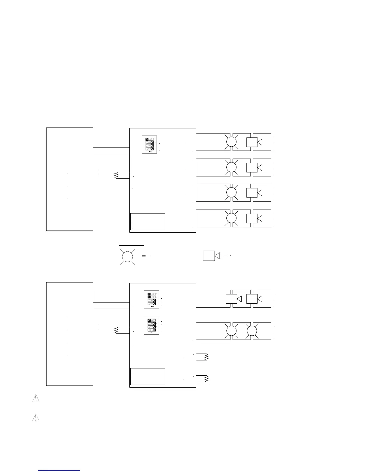
Example 1: NORMAL MODE (CLASS B)
POWERPATH
1
2
3
4
ON
OUT1-4
INPUT SELECT
TEMPORAL
STROBE SYNC
IN>OUT SYNC
OR EOLR
(2.2K OHMS)
LOGIC BOARD
SWI "OPEN"
SW2 "OPEN"
TO NEXT APPLIANCE
OR EOLR
+
-
IN1
RET1
-
+
OUT1
+
-
A
P
C
F
TO NEXT APPLIANCE
OR EOLR
(2.2K OHMS)
TO NEXT APPLIANCE
OUT2
-
+
TO NEXT APPLIANCE
OR EOLR
(2.2K OHMS)
+
-
OUT3
OR EOLR
(2.2K OHMS)
TO NEXT APPLIANCE
OUT4
-
+
STROBE
AUDIBLE
LEGEND
Example 2: TEMPORAL MODE (CLASS B)
POWERPATH
1
23
4
ON
OUT1
INPUT SELECT
TEMPORAL
STROBE SYNC
IN>OUT SYNC
LOGIC BOARD
SWI "OPEN"
SW2 "OPEN"
TO NEXT APPLIANCE
OR EOLR
+
-
IN1
RET1
-
+
-
+
OUT3
OUT4
TEMPORAL
OUT2-4
4
ON
2
1
3
INPUT SELECT
IN>OUT SYNC
STROBE SYNC
EOLR
2.2K OHMS
EOLR
2.2K OHMS
P
C
A
F
+
-
+
OUT1
-
TO NEXT APPLIANCE
OR EOLR
(2.2K OHMS)
TO NEXT APPLIANCE
OR EOLR
(2.2K OHMS)
OUT2
-
+
CAUTION: Strobes require constant voltage and will not operate properly in the TEMPORAL MODE. A second output set
in the NORMAL MODE will provide the constant voltage.
CAUTION: Only use audible appliances that can use a coded signal. Do not use with Wheelock Series AS/AH or
NS/NS4/NH appliances.
 Loading...