
W
william34Aug 15, 2025
Why is the AC LED off on my Wheelock Power Supply?
- RRobert KaiserAug 15, 2025
If the AC LED is off, it indicates there's no AC power. You should check the AC power source to ensure it's properly connected and functioning.
Why is the AC LED off on my Wheelock Power Supply?
If the AC LED is off, it indicates there's no AC power. You should check the AC power source to ensure it's properly connected and functioning.
What to do if horn, horn strobes, or strobes do not synchronize on Wheelock Power Supply?
If your horn, horn strobes, or strobes aren't synchronizing, it could be due to improper MODE selection or incompatible appliances. Verify the MODE selection and ensure that the appliances are the correct type for synchronization. If in IN>OUT MODE, check the input appliance (DSM, SM, or PS-12/24-8MP).
Why is the DC LED off on my Wheelock Power Supply?
If the DC LED is off, this indicates that there is no DC output. To resolve this, check the wiring to the AC power source.
What to do if CLASS “A” circuit is not functioning properly on Wheelock Power Supply?
If a CLASS “A” circuit isn't functioning correctly, the MODE selection or SW9 settings might be incorrect. Ensure the MODE selection is identical for each Class “A” output circuit. Remember that Class “A” OUT1 uses outputs 1 and 3, while Class “A” OUT2 uses outputs 2 and 4. Also, check that SW9 POS 1 and POS 2 on the board are in the “ON” position.
What to do if CLASS “B” circuit is not functioning properly on Wheelock Power Supply?
If a CLASS “B” circuit is not working as expected, the MODE selection or SW9 settings are likely incorrect. Check SW9 POS 1 and POS 2 on the board and ensure they are in the “OFF” position.
What to do if INP1, INP2 LED’s do not light in ALARM on Wheelock Power Supply?
If the INP1 and INP2 LEDs do not light up during an alarm, it means there is no input signal on terminals IN1+IN1- and IN2+IN2-. Check the input and input wiring to resolve this issue.
What does it mean if GND FAULT LED ON on Wheelock Power Supply?
If the GND FAULT LED is on, it indicates a ground fault. Check the output circuits to resolve the issue.
What to do if OUT1, OUT2, OUT3, OUT4 LED's are on during standby on Wheelock Power Supply?
If the OUT1, OUT2, OUT3, and OUT4 LEDs are on during standby, it indicates a trouble on the output. Check the output supervision voltage and the output EOLR (End Of Line Resistor).
How to fix no audible output in WHEELOCK SYNC MODE on Wheelock Power Supply?
If there is no audible output in WHEELOCK SYNC MODE, it could be due to no input to IN2+,IN2-. Check Example 13 and 14 for proper input connections.
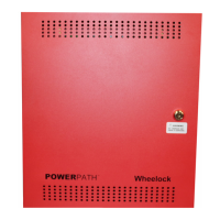
Provides an overview of the PS-12/24-8MP POWERPATH as a supervised remote power supply/charger for fire alarm systems.
Details the approvals, input power, output capabilities, and supervision features of the POWERPATH unit.
Defines key terms used in the manual, such as Class 'A', Class 'B', FACP, and EOLR, for clarity.
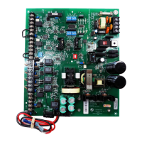
Identifies and describes the function of each terminal block on the POWERPATH unit for proper connection.
Lists and explains the status indicated by the various LED indicators on the POWERPATH unit.
Provides guidance on battery replacement intervals, types, and relevant calculations for system reliability.
Instructions for checking the POWERPATH unit for damage and ensuring all components are present after shipping.
Step-by-step guide for wiring the POWERPATH unit, including switch settings and terminal connections.
Explains how to connect the common trouble terminals for system monitoring and alert notifications.
Describes the different operational modes available for the POWERPATH outputs, such as Normal, Temporal, and Sync.
Details the DIP switch settings for configuring output modes, input selection, and synchronization for the unit.
Explains how to configure and wire the POWERPATH outputs for Class 'B' notification appliance circuits.
Explains how to configure and wire the POWERPATH outputs for Class 'A' notification appliance circuits.
Details how to synchronize multiple POWERPATH units using a master and remote configuration.
Outlines the terms and conditions of the manufacturer's limited warranty for the product's mechanical and electrical defects.
Specifies the limitations on Wheelock's liability concerning the product, including damages and software issues.
| Input Voltage | 120/240 VAC, 50/60 Hz |
|---|---|
| Output Current | 8 Amps |
| Battery Charger | Yes |
| Output Voltage | 12 or 24 VDC |
| Operating Temperature | 0°C to 49°C (32°F to 120°F) |
| Humidity | 0% to 93% non-condensing |