P84333 K Sheet 5 of 23
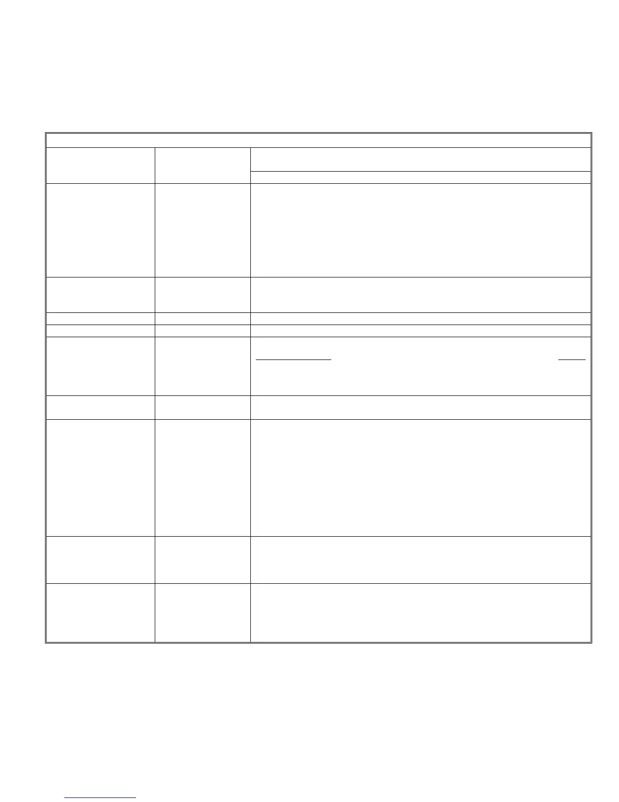
1.4 TERMINAL IDENTIFICATION
Table 1: Terminal Identification
Terminal Block
Identification
Terminal Function/Description
Numbers (Figure 1) Identification
TB4-1, 2
IN1+,IN1- These terminals connect to the input voltage source (i.e. 12VDC or
24VDC FACP). The FACP will supply a voltage from 8-33VDC at 5mA.
During the alarm condition these inputs will cause the designated outputs
to drive the notification appliances (designated outputs are set by output
DIP switch banks). During Stand-by on a FACP, a trouble condition on
the designated loop will cause these inputs to trip the FACP by opening
the FACP loop. Alarm condition always overrides trouble to drive output
indicating appliances.
TB4-3, 4,
RET1+, RET1- EOLR is connected on these terminals corresponding to IN1+ and IN1-,
or the loop may be continued to other power supplies or appliances
before terminating.
TB5-1, 2
IN2+, IN2- Same as IN1+, IN1- for corresponding terminals.
TB5-5, 4
RET2+, RET2- Same as RET1+, RET1- for corresponding terminals.
TB4-5, 6
C “DRY1” NC Dry contacts are used to actuate the designated outputs. Contacts are
normally closed
and actuate the power supply on contact Open.
Designated outputs correspond to IN1+,IN1-. NOTE: FACP NAC circuit
cannot energize the power supply by these contacts. NOTE: When these
terminals are not in use, a jumper must be connected across them.
TB5-5, 6
C “DRY2” NC Operates the same as IN2+,IN2- for corresponding terminals. When
these terminals are not in use, a jumper must be connected across them.
TB6-1, 2
TB6-3, 4
TB6-5, 6
TB6-7, 8
+OUT1-
+OUT2-
+OUT3-
+OUT4-
Indicating appliances are connected to these outputs (See Examples in
Operation Section). Each output can supply a maximum load of 3.0
Amps, Class "B" or 3.0 Amps Class "A" and can be individually
programmed for Normal Mode, Temporal Mode, IN>OUT SYNC Mode, or
WHEELOCK SYNC Mode. The outputs can be configured as four Class
"B" circuits, two Class "A" circuits, or two Class "B" and one Class "A"
circuits. Outputs are controlled by a designated input (INPUT 1 or 2) as
selected by the DIP switch for that output. NOTE: When the panel has
been set to synchronization mode, IN1 is used for strobe activation and
IN2 is used for audible silence. Individual output control is disabled.
TB7-1-3
“NO” “C” “NC”
(COMMON
TROUBLE
OUTPUT)
Typically used to trigger remote alerts or other reporting appliances.
Form C contacts rated 28VDC at 1 Amp.
TB7-4, 5
+ AUX - This output is capable of 3.5 Amps which can be used for door holders
and can be reset by a momentary switch on the board. The 3.5 Amps of
power is disconnected when AC power is lost or the unit is in alarm. The
3.5 Amps of power is reconnected 30 seconds after AC power returns or
the alarm condition is over.
 Loading...