P84333 K Sheet 15 of 23
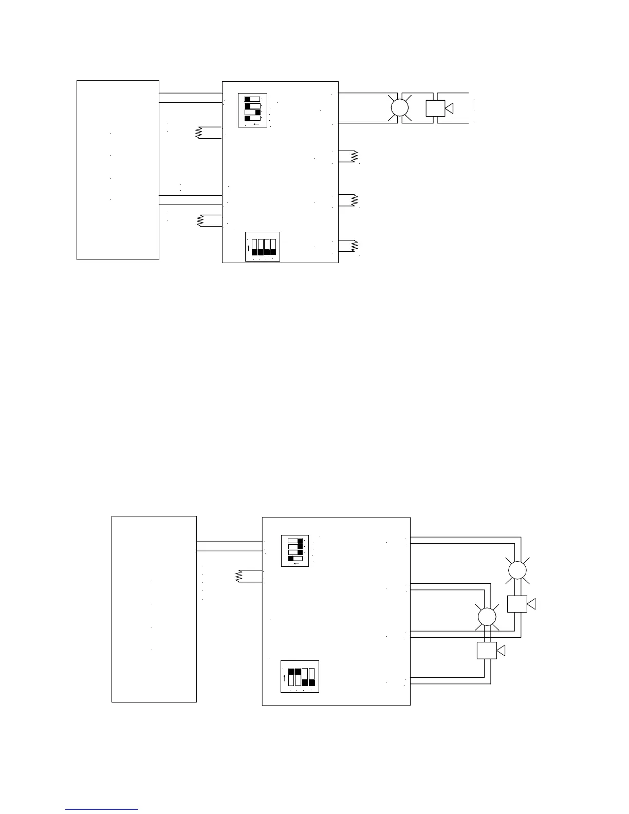
Example 7: WHEELOCK SYNC MODE with Audible Silence (CLASS B)
TO NEXT APPLIANCE
(2.2K OHMS)
OR EOLR
-
OUT1
+
+
-
2.2K OHMS
EOLR
-
+
+
-
2.2K OHMS
EOLR
2.2K OHMS
EOLR
OUT4
OUT3
OUT2
AUDIBLE
P
A
C
F
-
RET1
+
OR EOLR
TO NEXT APPLIANCE
SILENCE
-
+
IN1
-
+
IN2
+
RET2
-
TO NEXT APPLIANCE
OR EOLR
INPUT SELECT
TEMPORAL
WHEELOCK SYNC
IN>OUT SYNC
OUT1-4
POWERPATH
1
23
4
ON
1
23
4
ON
1
23
4
ON
1
2
3
4
ON
SW9
• This mode will only synchronize Wheelock horns, horn strobes, and strobes with the synchronization capability.
3.4 CLASS “A” OPERATION
Class “A” circuit 1 uses “OUT1” and “OUT3”. Class “A” circuit 2 uses “OUT2” and “OUT4”. When operating
in Class “A” the two circuits must have the same switch settings for the operational mode selected. Switch
SW9 position 1 & 2 on the PC board are in the “ON” position.
• IN1 and/or IN2 can be used for connection to the FACP. The INPUT SELECT Switch (1) selects which
input is to be used to activate the output.
• Board switch SW9 position 1 & 2 control Class “A” or Class “B” configuration. SW9 position 1 controls
Outputs 1 and 3. Switch SW9 position 2 controls Outputs 2 and 4.
• DIP Switch settings for each circuit in the Class “A” output must be set identically.
Example 8: NORMAL MODE (CLASS A)
POWERPATH
1
2
3
4
ON
OUT1-4
IN>OUT SYNC
WHEELOCK SYNC
TEMPORAL
INPUT SELECT
OUT4
OUT2
OUT3
+
-
-
+
OUT1
-
+
+
IN1
-
TO NEXT APPLIANCE
OR EOLR
RET1
+
-
F
C
P
A
OR RETURN
TO FACP
(CLASS "A")
-
+
1
2
3
4
ON
SW9
 Loading...