P84333 K Sheet 14 of 23
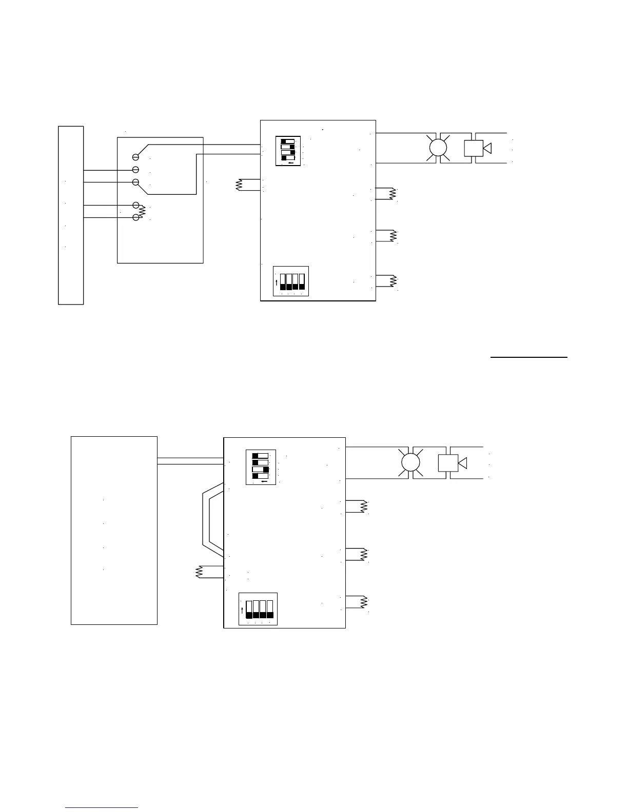
Example 5: IN>OUT SYNC MODE with External Sync Module with Audible Silence
(CLASS B)
POWERPATH
OUT1-4
IN>OUT SYNC
WHEELOCK SYNC
TEMPORAL
INPUT SELECT
TO NEXT
APPLIANCE
OR EOLR
-
+
IN1
-
+
RET1
+ OUT1
+ IN1
MINUS 1
+ AUDIBLE
SM/DSM
F
A
C
P
EOLR
- AUDIBLE
EOLR
2.2K OHMS
EOLR
2.2K OHMS
+
OUT4
-
+
OUT3
-
EOLR
2.2K OHMS
-
+
OUT2
+
-
OUT1
OR EOLR
(2.2K OHMS)
TO NEXT APPLIANCE
1
23
4
ON
1
23
4
ON
1
23
4
ON
1
2
3
4
ON
SW9
NOTE: When using the Wheelock external Sync Module (SM or DSM), synchronization will only occur
with
Wheelock sync appliances.
Example 6: WHEELOCK SYNC MODE without Audible Silence (CLASS B)
POWERPATH
OUT1-4
IN>OUT SYNC
WHEELOCK SYNC
TEMPORAL
INPUT SELECT
IN1
+
-
IN2
+
-
TO NEXT APPLIANCE
OR EOLR
+
RET2
-
P
C
A
F
RET1
+
-
-
OUT4
-
+
OUT3
+
OUT2
-
+
EOLR
2.2K OHMS
EOLR
2.2K OHMS
EOLR
2.2K OHMS
+
-
OUT1
TO NEXT APPLIANCE
OR EOLR
(2.2K OHMS)
1
23
4
ON
1
23
4
ON
1
23
4
ON
1
2
3
4
ON
SW9
• This mode will only synchronize Wheelock horns, horn strobes, and strobes with the synchronization capability.
• If only strobes are connected to the POWERPATH outputs, the initiating input to IN2 is not required.
• When synchronized horns are used on the two wire output of the POWERPATH, IN2 must be connected as
shown or the horns will not operate.
 Loading...