P84333 K Sheet 21 of 23
4.0 TROUBLESHOOTING:
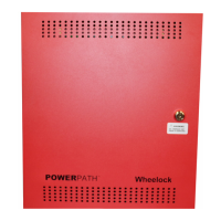
WARNING: THE PS-12/24-8MP POWERPATH CONTAINS VOLTAGES THAT CAN CAUSE DEATH OR
SERIOUS INJURY. ALWAYS OBSERVE PROPER ELECTRICAL SAFETY PRECAUTIONS AND WARNINGS.
Always follow good troubleshooting procedures:
• AUX power is available after a 30 second delay on power up and when coming out of alarm.
• When trouble occurs, observe all visual indications and note them.
• If the problem is obvious or it can be located on the Troubleshooting Table, note it.
• Press SYS RESET (SW8) and wait 30 seconds check for a trouble indication.
• Always de-energize the POWERPATH completely (Remove both AC and DC power) repairs.
• While the POWERPATH is de-energized, perform a visual and hands on check of all terminals and wires to
ensure proper termination.
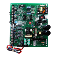
Table 4: Troubleshooting
Trouble Cause Action
INP1, INP2 LED’s do not light in
ALARM.
No input signal on terminals
IN1+IN1-, IN2+IN2-.
Check input and input wiring.
GND FAULT LED ON GND FAULT Check output circuits.
DC LED OFF No DC output. Check wiring to AC power source.
AC LED OFF No AC power. Check AC power source.
No audible output in
WHEELOCK SYNC MODE.
No input to IN2+,IN2-. See Example 13 and 14 for proper
input connections.
Horn, horn strobes, or strobes
do not synchronize.
Improper MODE selection
Improper appliances.
Check MODE selection.
Check appliances to ensure proper
type for synchronization. For
IN>OUT MODE check input
appliance (DSM, SM or PS-12/24-
8MP).
CLASS “A” circuit is not
functioning properly.
Improper MODE selection or
SW9 settings.
Check to be certain MODE
selection is identical for each Class
“A” output circuit. Class “A” OUT1
uses outputs 1 and 3. Class “A”
OUT2 uses outputs 2 and 4.
Check SW9 POS 1 and POS 2 on
board for “ON” position.
CLASS “B” circuit is not
functioning properly.
Improper MODE selection or
SW9 settings.
Check SW9 POS 1 and POS 2 on
board for “OFF” position.
OUT1, OUT2, OUT3, OUT4
LED's on during standby.
Trouble on output. Check output supervision voltage.
Check output EOLR.
 Loading...