EasyManua.ls Logo

Wheelock TPA-100 User Manual

Default Icon
7 pages
To Next Page IconTo Next Page
Page #1 background imageLoading...
Page #1 background image
273 Branchport Avenue
Long Branch, NJ 07740
(732) 222-6880
INSTALLATION INSTRUCTIONS
MODEL TPA-60/TPA-100
PAGING AMPLIFIERS
GENERAL APPLICATION INFORMATION
Wheelock's models TPA-60 and TPA-100 paging amplifiers are rated at 60 watts RMS and 100 watts RMS respectively.
These amplifiers afford a choice of five different inputs: two microphone inputs, one telephone input, and two background
music inputs. Only three of these inputs can be used actively at one time: one microphone, a choice of a second
microphone or telephone input, and a choice of one background music input applied through either AUX. 1 or AUX. 2.
Note that the background music will automatically be muted whenever a page is generated, from either a microphone or
telephone input.
An automatic volume limiter compensates for the varying voice levels and paging styles that may have access to a
system.
The amplifiers feature individual input volume controls, as well as a master volume control, individual treble and bass
controls, or low-cut horn protect switch, two input selector switches, an illuminated power on switch and a peak level
indicator.
Both models operate from 120 volts, 60Hz and have a power consumption of 180 watts (TPA-60) and 250 watts (TPA-
100). The units have an AC circuit breaker on the line input side, as well as a thermal breaker for overload protection on
the output. The AC circuit breaker is manually resettable. However, in the event it does not reset, have the trouble
investigated by an authorized service technician or return unit to the factory.
WARNING:
TO REDUCE THE RISK OF FIRE OR ELECTRIC SHOCK,
DO NOT EXPOSE THIS UNIT TO RAIN OR MOISTURE.
INSTALLATION
Unpacking
The amplifier was carefully checked before leaving the factory. Inspect shipping container and unit carefully for indication
of improper handling. If the unit has been damaged, make an immediate claim to the carrier.
Mounting Instructions
The amplifier is provided with a set of universal mounting brackets to facilitate either rack or surface wall mounting.
Remove the 8 screws (4 on either side) holding the cover to the chassis. Choose the mounting required (rack or surface
wall), and insert screws thru the universal mounting bracket and back into the cover/chassis holes as shown in Figures 1
and 2.
CAUTION: THESE DEVICES ARE NOT INTENDED FOR USE IN HAZARDOUS LOCATIONS AS DEFINED BY
THE NATIONAL ELECTRICAL CODE (NEC) AND BY THE NATIONAL FIRE PROTECTION ASSOCIATION
(NFPA).
P81932 H
SHEET 1 OF 7
RACK MOUNTING
Question and Answer IconNeed help?

Do you have a question about the Wheelock TPA-100 and is the answer not in the manual?

Wheelock TPA-100 Specifications

General IconGeneral
BrandWheelock
ModelTPA-100
CategoryAmplifier
LanguageEnglish

Summary

General Application Information and Safety

General Application Information

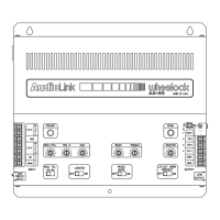
Details the Wheelock TPA-60 and TPA-100 paging amplifiers, their ratings, inputs, and features.

Electrical Safety Warning

Warning to reduce the risk of fire or electric shock by not exposing the unit to rain or moisture.

Installation Procedures

Unpacking and Inspection

Instructions for inspecting the shipping container and unit for damage upon arrival.

Mounting Instructions

Details on using universal mounting brackets for rack or surface wall mounting.

Hazardous Location Caution

Caution regarding the use of devices in hazardous locations as defined by NEC and NFPA.

Power and Grounding

Power and Grounding Requirements

Connects the 120 VAC line cord to a grounded outlet and importance of amplifier ground.

Input Connections

Telephone Input Connection

Connecting telephone wires to TIP and RING terminals, and setting the TEL/MIC 1 switch.

Microphone Input Connection

Connecting balanced low-impedance microphone wires to LO-Z terminals and shield to GND.

Microphone Cable Caution

Caution to use a shielded microphone input cable with the shield connected to GND to avoid interference.

High Impedance Inputs

Details on connecting AUX 1 and AUX 2 inputs, typically used for music or prerecorded sources.

Tape/Booster Output Connection

Connection for FM tuner, CD player or cassette to AUX 1 or AUX 2 inputs.

Output Connections and System Configuration

Output Connection to Speakers

Connect output wires to COM terminal for 25V or 70V constant voltage distribution.

PBX Isolation Caution

Caution to connect only to PBX incorporating isolation from the telecom network.

System Wattage Recommendation

Recommendation for future expansion: total system wattage should not exceed 85% of the amplifier's rated output.

Unused CO Trunk Port Connections

Instructions for connecting an amplifier to an unused CO trunk port using RPS-2406 power supply.

Operation Controls and Indicators

Control Operation Note

All controls rotate clockwise to increase and counterclockwise to decrease.

Power Switch and Indicator

Describes the illuminated power switch and its indicator light function.

Master Volume Control

Sets the total output level of the amplifier without affecting individual input levels.

Telephone/Microphone 1 Selector

Switches between telephone input paging and MIC 1 input paging.

Auxiliary Input Selector

Selects between AUX 1 or AUX 2 program source inputs.

Telephone/Microphone 1 Volume

Adjusts the volume for the telephone paging or MIC 1 paging input.

Microphone 2 Volume Control

Adjusts the volume of the MIC 2 paging input.

Auxiliary Input Volume Controls

Adjusts the volume of the AUX 1/AUX 2 inputs for music or tone signaling.

Tone Controls Adjustment

Sets individual Bass and Treble controls for optimum tonal balance of the output signal.

Music Mute Functionality

Music is automatically muted when paging and gradually returns to original level afterward.

Peak Indicator Function

Flickering LED at max levels is normal; a permanently lit LED indicates an overdrive condition.

Horn Protection / Lo-Cut Switch

Protects horns from low frequencies; turn switch ON when horns are used in the system.

Maintenance and Warranty

Maintenance Caution

Caution that there are no user-replaceable parts and all internal servicing must be done by a qualified technician.

Limited Warranty Information

Refers to Wheelock's Terms and Conditions of sale for warranty details.

Related product manuals