Page 3
Audio signals (J15):
Radio Rebroadcast (Pins 1, 5)
Two blue wires are used to connect the audio output of your two-way radio
to the Whelen Siren Module for radio rebroadcast. This is an optional
connection.
NOTE: Radio rebroadcast will NOT work with radios requiring
amplified remote speakers! If your remote speaker is amplified (i.e.
contains a power amp circuit in the speaker assembly), the signal
from the radio will not be appropriate for this input.
Locate the two wires that connect the external speaker to the two-way
radio. Splice one of the blue wires into one of the radio’s speaker wires,
then splice the other blue wire into the other radio speaker wire.
Radio Repeat Volume Adjustment
Locate the Radio Repeat adjustment potentiometer on the left side of the
Core module. Set the volume of the vehicle’s two-way radio to its normal
operating level. Press the RAD button on the control head to activate
Radio Repeat. As incoming transmissions are received, adjust the Radio
Repeat potentiometer to set the desired level. Turn the potentiometer
clockwise to increase the level and counter-clockwise to decrease the
level.
Auxiliary Audio Input (Pins 2,6)
Two green wires are proved to connect the auxiliary audio output of an
appropriate Whelen device to this unit.
Cabin Speaker (Pins 3,7)
The cabin speaker is used to preview tones and messages at a low
volume level. The yellow wire goes to the positive (+) speaker terminal,
and the white-yellow wire goes to the negative (-) speaker terminal.
Auxiliary Audio Output (Pins 4,8)
The white-violet and violet wires are used to connect the audio output of
this unit to the auxiliary audio input of a compatible Whelen device.
Microphone (J7):
Attach the microphone extension cable to this connector, route the cable
to the desired location in the vehicle and secure the other end to a fixed
location and then attach the microphone.
PA Volume Adjustment
To adjust the PA volume refer to the WeCan Command software for
instructions.
Control Head Connection (J21):
Attach the supplied extension cable to J21 and route it to the location
desired for the control head, attach the other end to the control head
coupler and attach the control head to the coupler.
USB “C” programming Port (J9):
Attach to computer when programming the system with the Command™
Software.
USB Host Port (J8) :
To be used with a Whelen USB device.
Ethernet Port (J13):
To be used with a Whelen Ethernet device.
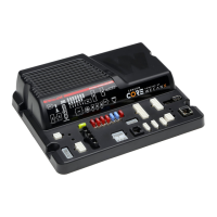
CAN Communications (J18, 19 & 20):
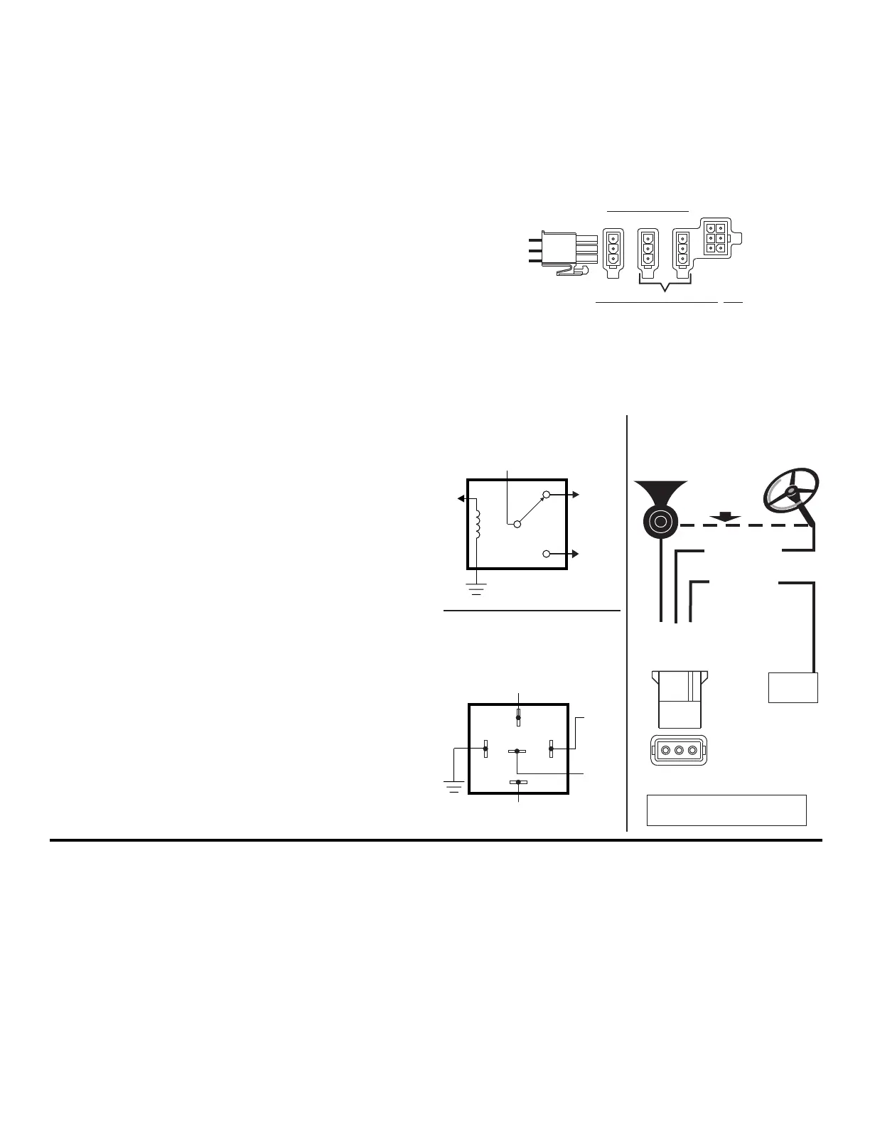
Hands-Free Siren / Optional
You may either use a customer supplied relay capable of handling the
current of your vehicle horn connected as shown or the Dry Contact Relay
located on the main control box
(recommended)
J18J19 J20
CAN INPUTSCAN INPUTS
C AN I N PUTS
pConnects to Vehicle CAN orts
J19 - Primary J20 - Secondary
To WeCanX
Connecting the USB:
In order to fully configure your system, you need to connect USB and open
Command software. If you plan to check for firmware updates, detect
devices to build a new configuration, assign installation IDs or want all
devices to accept the full configuration immediately after transfer, then you
need to follow the bootup and initialization process first. All devices need to
be powered and connected to Core via WecanX connector before power
and ignition are applied to main Core. Once the boot-up and initialization
process are completed, USB can be connected from a computer with
Command software.
Note: Make sure power is applied to core before connecting USB.
If you are just transferring a new configuration, extracting a configuration,
or updating the firmware of the main Core controller only, all you need to
do is connect USB to Core via USB C connector without external power.
This provides communication and power to the main controller only. If
there is no configuration currently on Core, the Status indicator will rapidly
blink Red signifying no main power/ignition as well as no configuration. If
there is a valid configuration, the Status indicator will rapidly blink Green to
signify no main power/ignition as well as a valid configuration. If there is no
OBDII or analog connections the Activity indicator will be steady Blue.
Note: If you send a configuration to Core with only USB connected,
the configuration will not be sent to all devices until power and
ignition are applied to Core with WecanX connection maintained to
powered devices.
Booting up Core:
When you first apply power and ignition to Core, the Status indicator will
blink Magenta to indicate that it is booting up the application code. After
Bosch™ Style
(Tyco-P&B P/N:VF4-45F11)
(customer supplied)
Dry Contact Relay
Switched as output 23
(recommended)
To Vehicle Car Horn
From Vehicle
Horn Relay
ToAny Output
To any Input configured
as Horn Ring
30
87A
85 86
87
Generic Style Relay
(customer supplied)
ToAny Output
ToanyInput
configured as
Horn Ring
To Vehicle
Car Horn
NO
NC
From Vehicle Horn Relay
J11
DRY CONTACT
RELAY
HORN RING
Cut connection
between horn ring
and factory horn
3 - ORG
2 - RED
1 - BRN
Norma
lly Closed - T
o
Vehicle Car Horn
COMMON - From
Vehicle Horn Relay
Normally Open
Horn Ring Input
If the horn
connection is
positive 12V, the
load should not
exceed 10 AMPS.
To Transfer Horn for HF, activate
J11 - 1, 2, 3 dry contact configuration
VEHICLE
HORN
To Input 1
WHT/BRN
 Loading...