Do you have a question about the Whelen Engineering Company SA315 and is the answer not in the manual?
Covers opening the hood, removing covers, and initial bracket securing steps.
Details the use of Rivnuts, marking, drilling, and installation for securing the bracket.
Explains how to attach the siren speaker to the mounting bracket using specific hardware.
Connect speaker wires to the amplifier and reinstall protective covers.
Alerts users to potential hearing damage and outlines technician responsibilities for product operation.
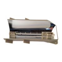
This document outlines the installation and maintenance procedures for the SA315 Siren Speaker Bracket, designed for 2007-2009 Suburban/Tahoe vehicles. The SA315 Siren Speaker Bracket is a specialized mounting solution that facilitates the secure installation of a siren speaker within the engine compartment of compatible vehicles. Its primary function is to provide a stable and correctly oriented platform for the siren speaker, ensuring optimal performance and longevity. The bracket is engineered to integrate seamlessly with the vehicle's existing structure, utilizing specific mounting points to achieve a robust and reliable installation.
The SA315 Siren Speaker Bracket serves as an intermediary mounting component between the siren speaker and the vehicle's radiator support. Its core function is to position the siren speaker in a location that maximizes sound projection while minimizing interference with other engine compartment components. The design accounts for critical factors such as drainage and structural integrity, which are essential for the speaker's operational efficiency and lifespan. By providing a dedicated and secure mounting point, the bracket ensures that the siren speaker remains firmly in place, even under demanding driving conditions, and that its sound output is directed effectively. The bracket's design also considers the need for proper wire routing, with a designated wire exit and drain hole to prevent water accumulation and protect electrical connections. This attention to detail is crucial for maintaining the speaker's functionality and preventing premature failure due to environmental exposure. The bracket is an integral part of a complete siren system, enabling the effective deployment of emergency warning tones.
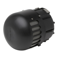
The installation process for the SA315 Siren Speaker Bracket involves several key steps, beginning with accessing the engine compartment by removing the protective cover. The bracket is then secured to the passenger side radiator support using an existing bolt and additional mounting points. A critical aspect of the installation is the use of Rivnuts™, which are specialized fasteners requiring a dedicated installation tool. This method ensures a strong and durable connection to the vehicle's frame. The document emphasizes the importance of precise drilling and proper Rivnut™ installation to achieve the intended structural integrity. Once the bracket is in place, the siren speaker is attached to it using supplied hardware, including specific hex head screws and lockwashers. The orientation of the siren speaker on the bracket is crucial for optimal performance and drainage. The document explicitly states that the speaker must be oriented so that the wire passage/drain hole is in the "6 o'clock" position (closest to the road). This specific orientation is vital to prevent water accumulation within the speaker, which could lead to premature driver failure and void the product warranty. After the speaker is mounted, its wires (WHITE for positive and BLACK for negative) are extended to the siren amplifier and connected according to the amplifier's instructions. A functional test of the siren is recommended to confirm proper operation before reinstalling the protective cover and returning the vehicle to service. The document also highlights the importance of ensuring that the installation does not interfere with or compromise the operation or efficiency of any other vehicle equipment. A visual confirmation of the proper operation of all vehicle components/equipment is advised before returning the vehicle to active service.
While the document primarily focuses on installation, it implicitly addresses maintenance through its emphasis on proper installation techniques designed to prevent common issues. The critical instruction regarding the speaker's orientation for drainage is a prime example of a built-in maintenance feature. By ensuring the drain hole is correctly positioned, the bracket helps to prevent water ingress and accumulation, which are significant causes of speaker damage and failure. This proactive measure reduces the need for reactive maintenance related to water damage. The use of robust hardware, such as hex head screws and lockwashers, contributes to the long-term stability of the installation, minimizing the likelihood of loosening or detachment over time. The document also stresses the importance of using the correct tools and following precise instructions for Rivnut™ installation, which ensures a secure and lasting mount, thereby reducing the need for re-tightening or repair. Although not explicitly stated as a maintenance task, the recommendation to test the siren after installation serves as an initial check to ensure all components are functioning correctly, which can prevent future operational issues. The general advice to ensure the installation does not interfere with other vehicle components also contributes to overall vehicle health and reduces potential maintenance problems arising from improper integration. The warranty information provided at the end of the document further underscores the importance of correct installation and usage, as improper handling or installation could void the warranty, effectively making maintenance a user responsibility in such cases. Adhering to the detailed installation steps is the primary "maintenance" action prescribed by this manual, as it aims to create a durable and trouble-free setup.
| Brand | Whelen Engineering Company |
|---|---|
| Model | SA315 |
| Output Power | 100 watts |
| Voltage | 12 VDC |
| IP Rating | IP67 |
| Current Draw | 8 Amps |