5 - SET-UP FOR OPERATION
0812_GB_42 - GAS KITCHENS 04/2008
5.3 Replacing parts
All parts must be replaced by authorized technicians
only!
To replace the following parts first remove all the control knobs and
control panel (after loosening the fixing screws), then extract the
ignition wire.
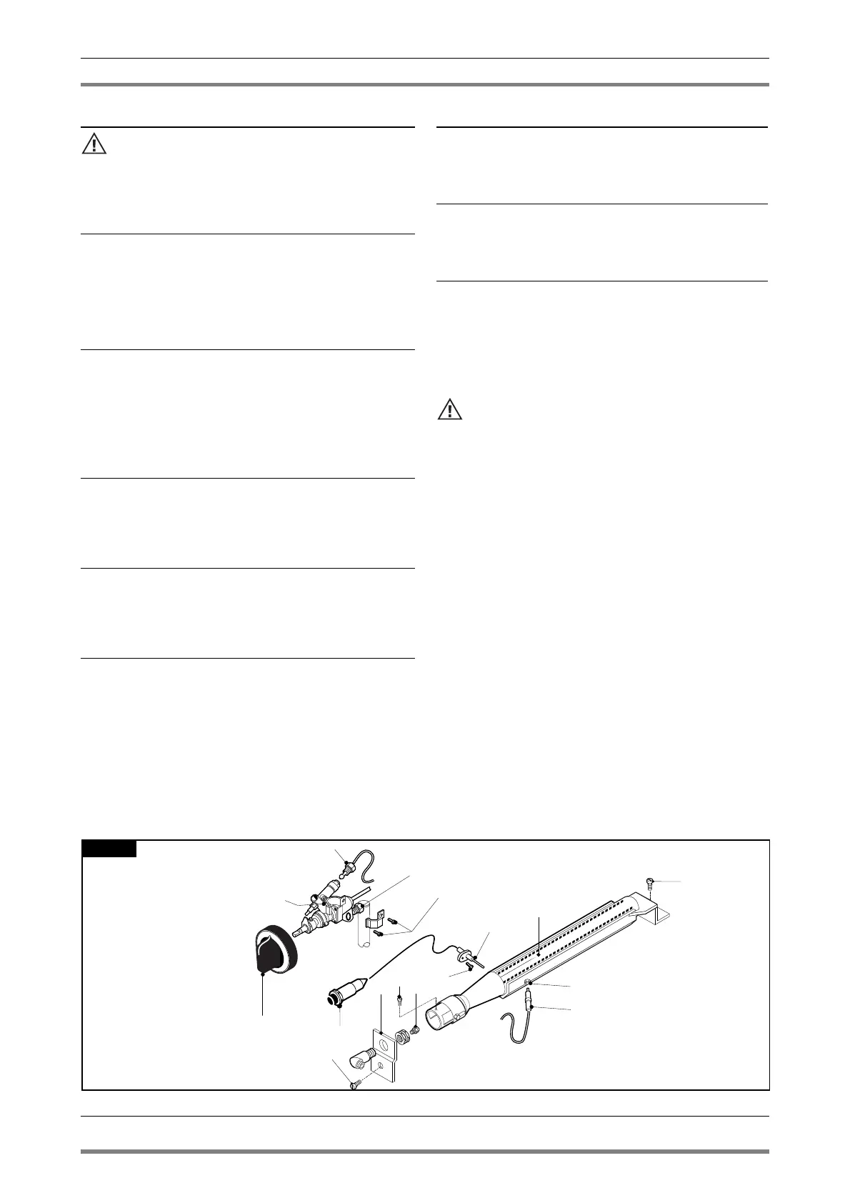
5.3.1 Open flame gas cock
Loosen the fitting of the pipes (pos. 9 fig. 1) of the gas, unfix the
graft (pos. 8 fig. 1) of the thermocouple, unscrew the two screws
(pos. 6 fig. 1) fixing the cock on the gas piping through the hanger
(pos. 7 fig. 1) and replace the piece (pos. 17 fig. 1) install in reverse
order install paying attention to the seal ring. After the replacement
check the seal using a leack detetctor spray.
5.3.2 Open flame gas burner
Remove with the help of a screwdriver the spring (pos. 18 fig. 1)
blocking the gas pipe and slip off it from burner seat, unscrew the
screws (pos. 12 fig. 1) fixing the injector-holder cup (pos. 4 fig. 1), pull
down the cup, unfix the thermocouple and the plug (pos. 11 and 15
fig. 1) and replace the piece install in reverse order. After replacement,
check injector, see table 1 and do a seal check using a leak detector
spray.
5.3.3 Open flame thermocouple
Unfix the graft (pos. 8 fig. 1) fixing the thermocouple on the cock,
unscrew the screws (pos. 12 fig. 1) fixing the injector-holder cup
(pos. 4 fig. 1), pull down the cup, unfix the thermocouple (pos. 11
fig. 1) and replace the piece install in reverse order.
5.3.4 Open flame plug
Unfix the cable (pos. 16 fig. 1) from the piezo ignition, unscrew the
screws (pos. 12 fig. 1) fixing the injector-holder cup (pos. 4 fig. 1),
pull down the cup, unfix the plug (pos. 15 fig. 1) and replace the
piece install in reverse order.
5.3.5 Gas cock gas oven GN 1/1
Loosen the fittings (pos. 10 and 11 fig. 2) which are for the connec-
tion for the gas pipe and the thermocouple, unscrew the screws
(pos. 12 fig. 2) remove the coil of the thermostat from its place in
the cooking chamber and put in a new piece in the reverse order.
After the replacement check the seal using a leack detector spray.
5.3.6 Plug gas oven GN 1/1
Unscrew the fastening screws and remove the lower panel, extract
the ignition wire and unscrew the screws (pos. 13 fig. 2) and put in
a new piece (pos. 16 fig. 2) install in reverse order.
5.3.7 Thermocouple gas oven GN 1/1
Unscrew the nut (pos. 20 fig. 2) and the nut (pos. 10 fig. 2) fixing
the thermocouple on the cock and put in a new piece (pos. 17 fig.
2) install in reverse order.
5.3.8 Main burner gas oven GN 1/1
Remove the front/lower panel by removing the fastening screws.
Unscrew the screws fixing the hanger (pos. 2 fig. 2) of the injector-
holder (pos. 3 fig. 2), unscrew the screw (pos.5 fig. 2) and extract
the injector-holder from its housing, unscrew the screws rear fixing
(pos. 19 fig. 2) of the burner and put in a new piece in the reverse
order. After the replacement check the seal using a leack detector
spray.
After any maintenance or repair work, replace the con-
trol panel and the lower panel.
After replacing gas input components, check operation
again and test for leakage.
10 · 16