5 - SET-UP FOR OPERATION
0804_GB_42 - GAS FRY TOP 04/2008
5.1.5 Power check for operation with liquid gas
Check if the type of injectors used meet the data of the table 1.
Check that the pressure reducer installed in the system has an outlet
pressure which is compliant with paragraph 5.1.2 "Check of power"
(can be checked on the data plate of the appliance or on the table
1).
5.1.6 Operation control
• Start the appliance in accordance with the instructions.
• Check that the appliance does not have any leaks by using a leak-
detecting spray.
• Check ignition and that flame on the main burner lights properly
and is correctly formed, even on low.
• A servicing and maintenance contract is recommended.
5.1.7 Checking the primary air
The burners are equipped with primary air adjustment. Distance “A”
(fig. 2A and fig. 2B) see table 1.
Air volume flow is correct when there is sufficient protection against
the flame rising when the burner is cold or in case of flashback
when the burner is hot.
5.1.8 Operator training
• Explain and show the user how the machine works according to
the instructions, and hand him this manual.
• Remind the user that any structural alterations or any building
modification or renovation may affect the combustion air supply,
thus requiring a second operation check.
5.1.9 Conversion and adjustment
To change over form one kind of gas to another, for example from
methane to liquid gas, or to another type of gas, the use of suitable
injectors for the main burner is required, in accordance with the
table 1.
The injectors of the main burners for different types of gas, marked
with the relative diameter in hundredths of mm, are in an envelope
which is provided with the appliance. If injectors are not available
please contact the factory with model and serial number written on
technical data sticker. After transformation or adaptation, carry out
operating checks as described in paragraph 5.1.6 “Operation con-
trol”.
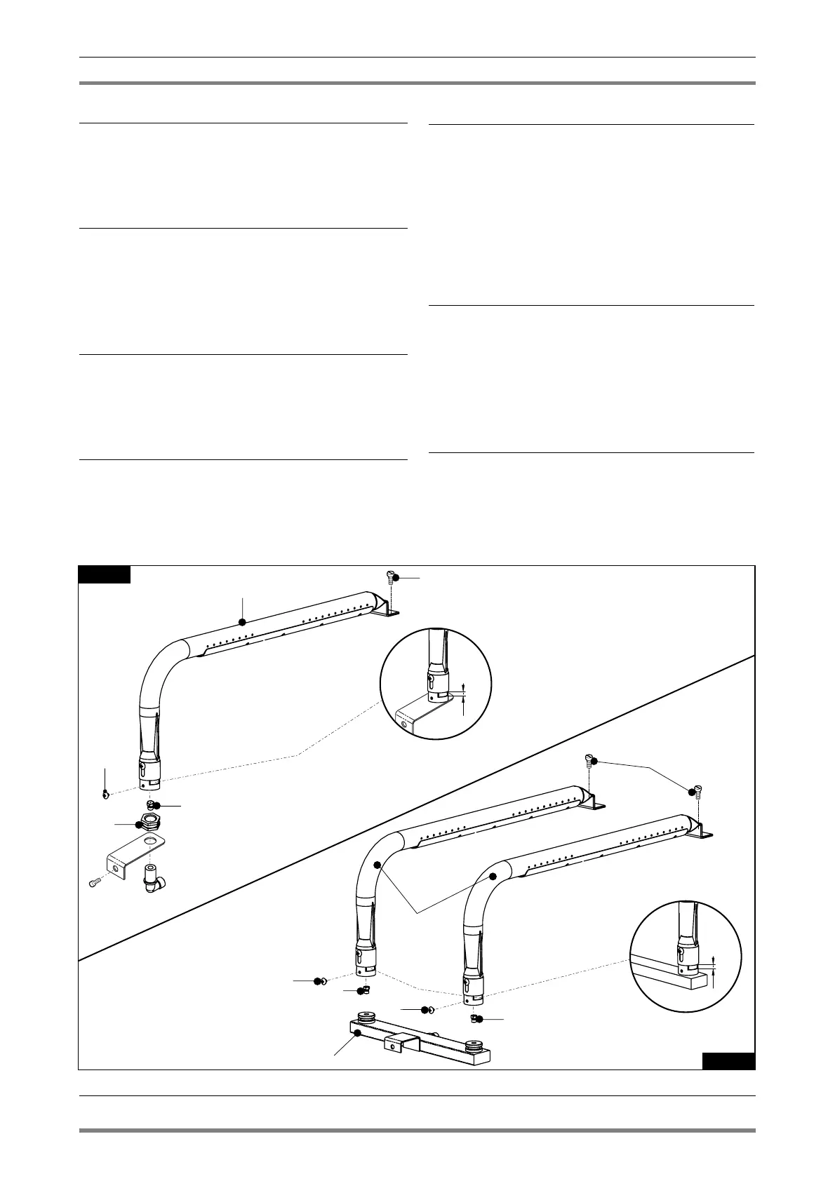
5.1.10 Replacement of burner injector fry top 400
To replace the injector (pos. 1 fig. 2A) unscrew the screw (pos. 2 fig.
2A) fixing the burner (pos. 3 fig. 2A) to the injector-holder nut (pos.
4 fig. 2A), lift up the burner until catch up the injector and replace
the injector with one able for the type of gas, see table 1, install in
reverse order.
After fitting the new injectors, reset primary air distance “A” (fig.
2A) see table 1, and fasten the bushing with the appropriate screw.
After the replacement check the seal using a leack detector spray.
5.1.11 Replacement of burner injectors fry top 600
To replace the injectors (pos. 1 fig. 2B) unscrew the screws (pos. 2
fig. 2B) fixing the burners (pos. 3 fig. 2B) to the injector-holder col-
lector nuts (pos. 4 fig. 2B), lift up the burners until catch up the
injectors and replace the injectors with one able for the type of gas,
see table 1, install in reverse order.
After fitting the new injectors, reset primary air distance “A” (fig.
2B) see table 1, and fasten the bushing with the appropriate screw..
8 · 12