14
2. Remove four screws attaching the terminal box cover.
3. Determine which direction (front or rear) the home power
supply cable will enter the terminal box. Remove the
appropriate knockout from the front or rear panel and install a
1/2" (1.3 cm) UL listed or CSA approved conduit connector.
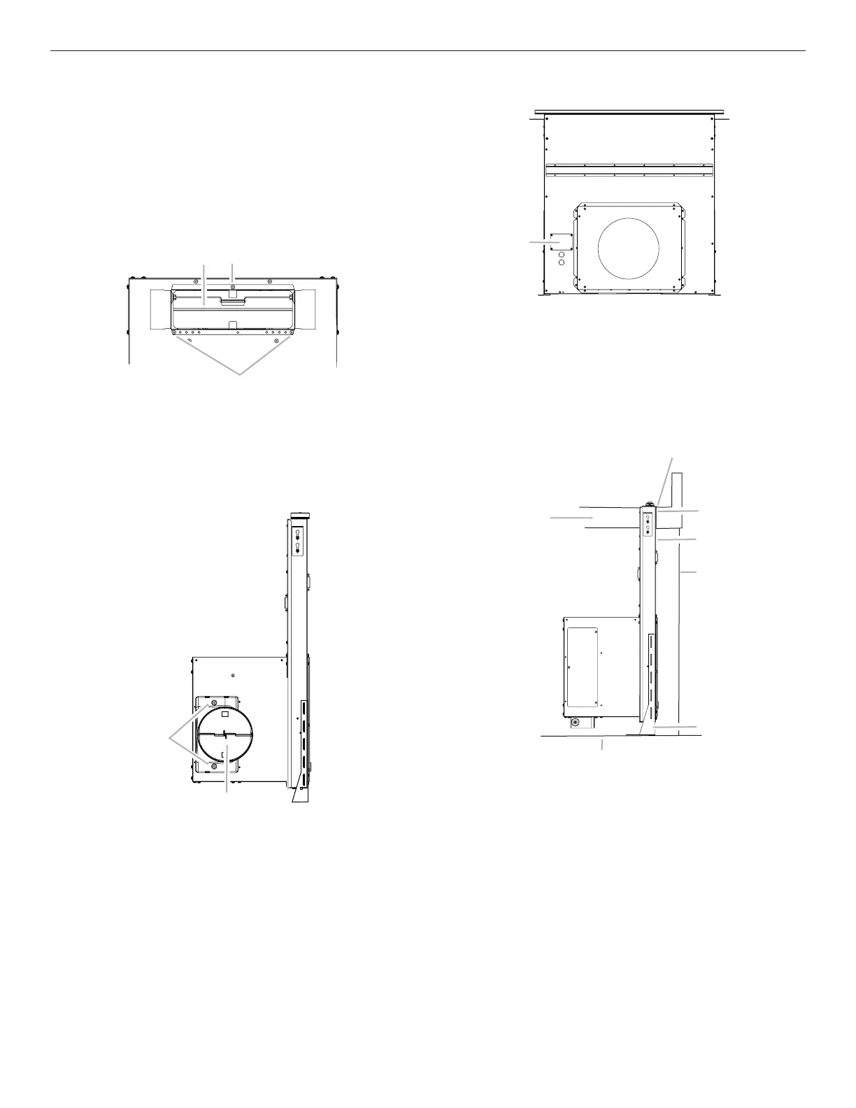
4. Using two or more people, insert the downdraft vent into the
countertop cutout. Position downdraft vent so it is centered
in the cutout with the rear ange over the edge of the cutout
and the rear of the vent box against the edge of the cutout.
A. Terminal box cover
E
A. Rear ange of downdraft vent
B. Edge of cutout in countertop
C. Rear of downdraft vent
D. Cabinet back
E. Lower support leg
F. Cabinet oor
G. Countertop
NOTE: The downdraft vent system is supplied with a 3
1
/
4
" x 10"
(8.3 cm x 25.4 cm) backdraft damper and a 6" (15.2 cm) round
vent transition with damper. Refer to “3
1
/
4
" x 10"
(8.3 cm x 25.4 cm) Backdraft Damper” or “6" (15.2 cm) Round
Vent Transition with Damper,” depending upon the type of venting
you are using.
3
1
/
4
" x 10" (8.3 cm x 25.4 cm) Backdraft Damper
1. Attach the 3¼" x 10" (8.3 cm x 25.4 cm) backdraft damper
to the vent opening in the blower motor box, using three
3.5 x 9.5 mm screws.
6" (15.2 cm) Round Vent Transition with Damper
1. Attach the 6" (15.2 cm) round vent transition to vent opening
(left- or right-side venting only is recommended), using two
3.5 x 9.5 mm screws.
A
A. 3.5 x 9.5 mm screws
B. 3¼" x 10" (8.3 cm x 25.4 cm) backdraft damper
A. 3.5 x 9.5 mm screws
B. 6" (15.2 cm) round vent transition with damper
Complete Installation