14
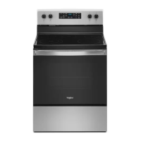
Electrical Connection Options
If your home has:
And you will be
connecting to:
Go to Section:
4-wire receptacle
(NEMA type 14-50R)
A UL Listed, 250 V
minimum, 40 A,
range power
supply cord
4-wire connection:
Power supply cord
4-wire direct
A circuit breaker
box or fused
disconnect
4-wire connection:
Direct wire
3-wire receptacle
(NEMA type 10-50R)
A UL Listed, 250 V
minimum, 40 A,
range power
supply cord
3-wire connection:
Power supply cord
3-wire direct
A circuit breaker
box or fused
disconnect
3-wire connection:
Direct wire
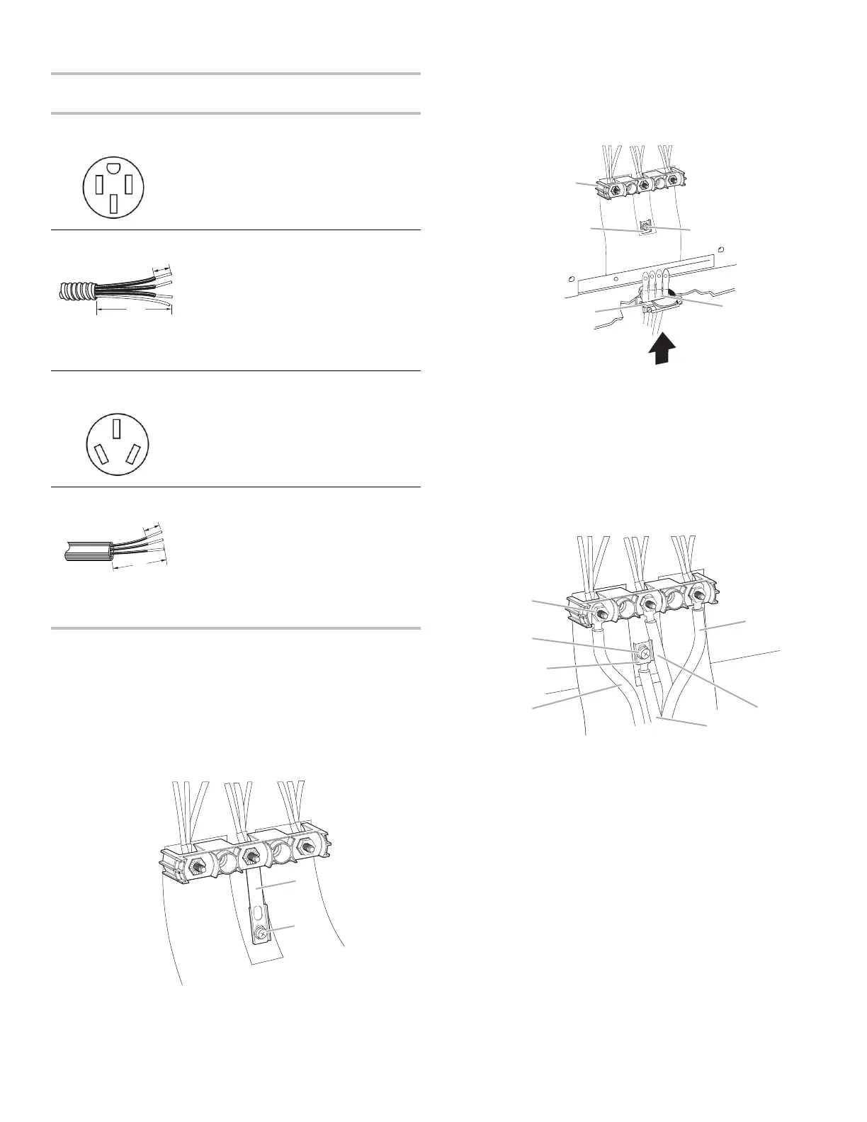
4-Wire Connection: Power Supply Cord
Use this method for:
� New branch-circuit installations (1996 NEC)
� Mobile homes
� Recreational vehicles
� In an area where local codes prohibit grounding through the
neutral
1. Part of Ground-link strap must be cut out and removed.
A. Ground-link strap
B. Ground-link screw
2. Use a Phillips screwdriver to remove the ground-link screw
from the back of the range. Save the ground-link screw and
the end of the ground link under the screw.
3. Feed the power supply cord through the strain relief on the
cord/conduit plate on bottom of range. Allow enough slack to
easily attach the wiring to the terminal block.
A. Terminal block
B. Ground-link
screw
C. UL listed strain relief
D. Power supply cord wires
E. Ground-link strap end piece
4. Use Phillips screwdriver to connect the green ground wire
from the power supply cord to the range with the ground-link
screw. Insert the ground-link screw through the ground-link
strap end piece and the green ground wire. The ground wire
must be attached first.
5. Use 3/8" (9.5 mm) nut driver to connect the neutral (white)
wire to the center terminal block post with one of the 10-32
hex nuts.
A. 10-32 hex nut
B. Ground-link
screw
C. Line 2 (red)
D. Green ground wire
E. Neutral (center) wire
F. Line 1 (black)
G. Ground-link strap end piece
6. Connect line 2 (red) and line 1 (black) wires to the outer
terminal block posts with 10-32 hex nuts.
7. Using a torque wrench, tighten the hex nuts to a
recommended torque of 20 in-lbs (2.3 N-m).
NOTE: For power supply cord replacement, use only a power
cord rated at 250 V minimum, 40 A or 50 A that is marked for
use with nominal 1
3
⁄
8
" (3.5 cm) diameter connection opening,
with ring terminals and marked for use with ranges.
8. Tighten strain relief screws.
IMPORTANT: Verify the tightness of the hex nuts.
9. Replace terminal block access cover.
10. Reconnect power.
A. 3/8" (1 cm)
B. 5" (12 cm)
A. 3/8" (1 cm)
B. 3" (7.6 cm)
 Loading...