QUICK START
To connect your 4926 unit as quickly as possible, without having to read
the entire manual, just follow these steps.
1. Using the 4 mounting screws provided, mount the unit into your rack. Do not plug
the unit in.
2. Set the AC voltage back panel switch to the appropriate 115 or 230VAC setting.
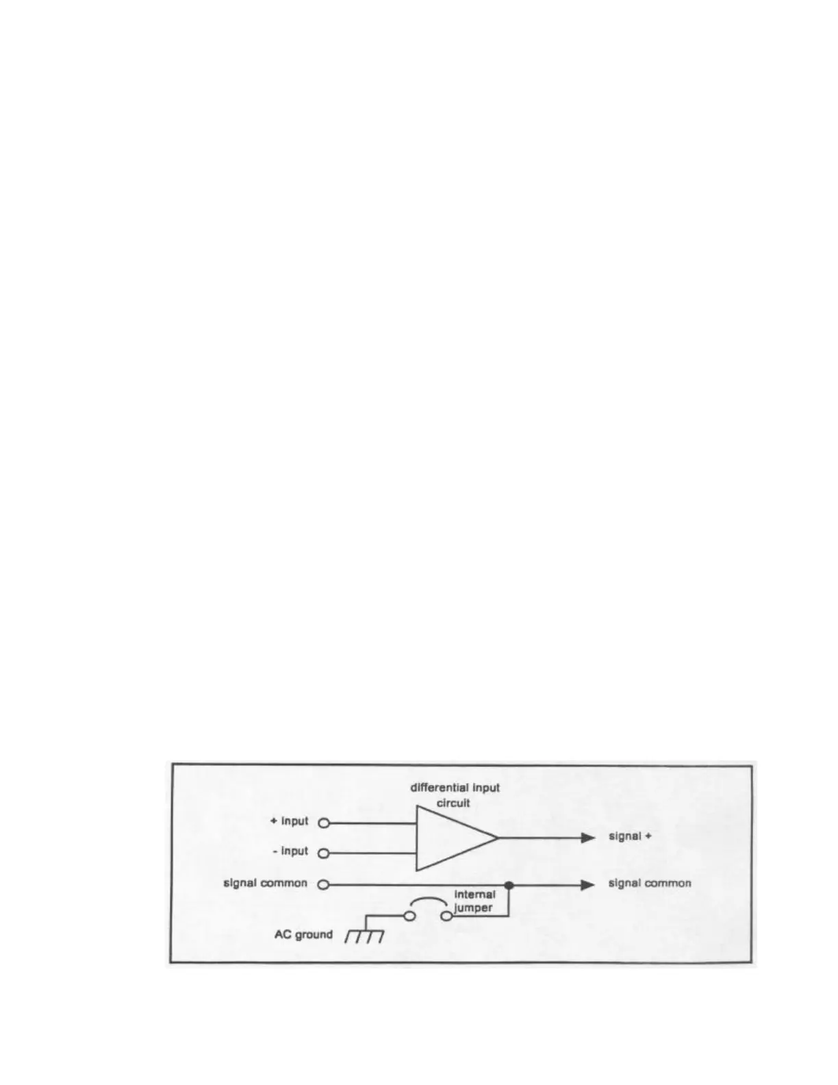
3. Connect the input channel(s) for either balanced or unbalanced operation, paying
careful attention to the connections shown in Figure 1. Note: For unbalanced
operation, audio negative must be connected to signal common, otherwise a 6 dB
loss in signal level will result.
4. Connect the output cables for either balanced or unbalanced operation, paying
careful attention to the connections shown in Figure 2. Note: For unbalanced
operation, audio negative must be connected to signal common, otherwise a 6dB
loss in signal level will result.
5. Set the output assignments by setting the 2 left-most levers in each 7 position
output DIP switch to the desired signal routing configuration. A channel is ”on” if
its lever is up.
6. Check all signal connections. It is good practice to initially set the input signal
gain to unity (input DIP switch levers all up) on both inputs and the output
attenuation to 31 dB (output DIP switch levers all down) on all outputs. This will
help prevent overdriving any devices connected to the 4926 at initial power-up.
Plug the unit in.
7. Set the input gain and output attenuation to the desired setting. For example, 11
dB of gain would require the 8, 2 and 1 levers to be pushed down. For gain
adjustments, it is good practice to reset the DIP switch lever settings to the ”up”
position before entering the new gain setting. For attenuation adjustments, it is
good practice to reset the DIP switch levers to the ”down” position before
entering the new attenuation setting. These procedures prevent excessive output
signal amplitudes during level setting. Remember: It is desirable to use as little
output attenuation as possible when setting the 4926 gain structure. This
maximizes the 4926 dynamic range and reduces noise.
Figure 1 - Input Connections
 Loading...