REAR PANEL FEATURES
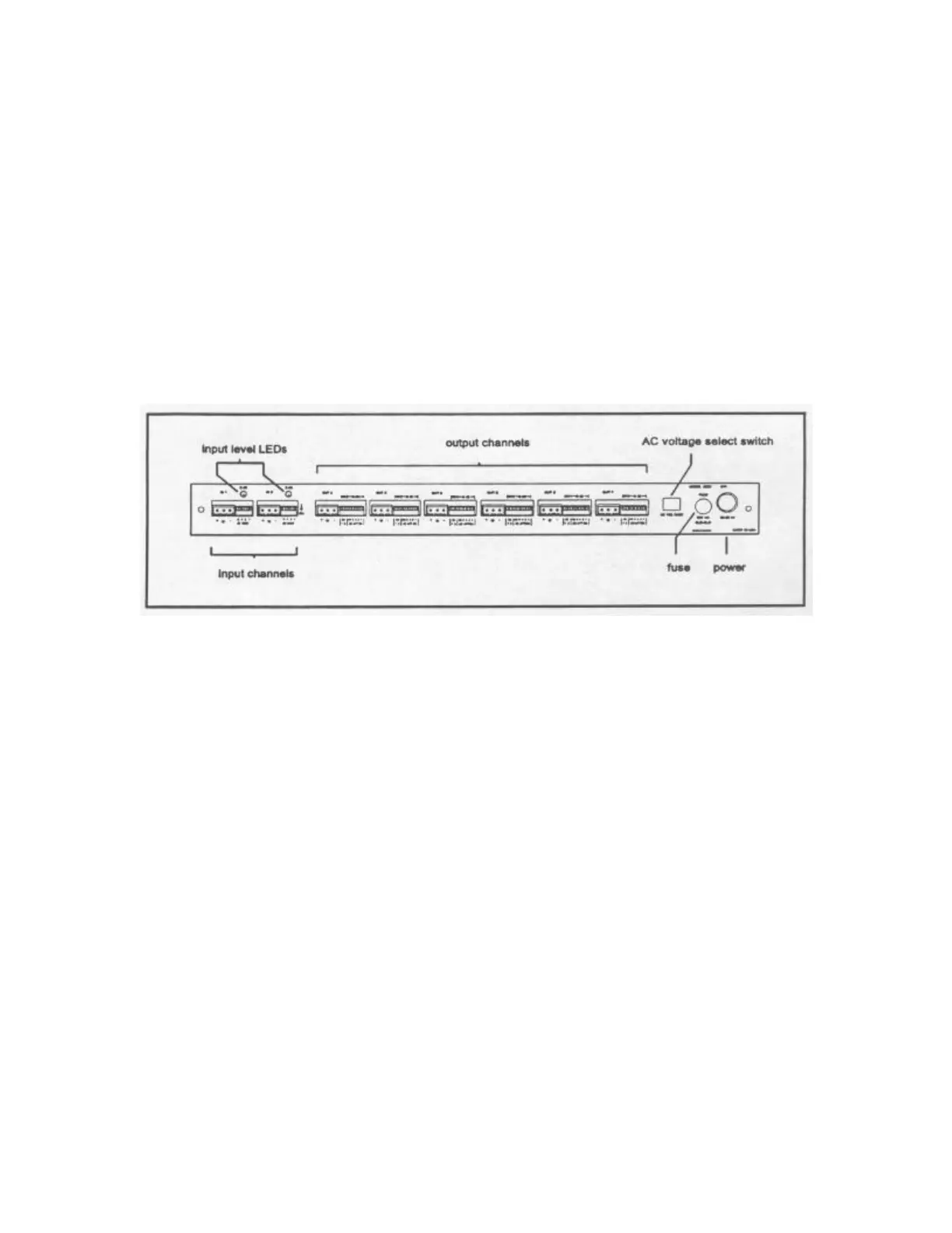
Each input and output in the 4926 is electronically balanced and interfaced with
removable screw terminal connectors. Input gain is set using a 4 lever DIP switch and
output attenuation is set using 5 of the 7 levers in each output DIP switch. Above each
input gain switch is a 0 dB calibration LED. Output assignments are made using the 2
remaining levers in each 7 position output DIP switch, which allow selection of
individual input channels or a sum of both inputs. The back panel also houses the AC
voltage select switch and the fuse holder. Figure 4 identifies all of the 4926 rear panel
features.
For convenience, a functional block diagram of the 4926 is provided on the unit top
panel.
SOUND SYSTEM CONNECTIONS
This manual is not intended to provide an exhaustive explanation of sound system
connections, however, in the interest of getting the absolute best performance from your
4926, a brief summary is given below.
NEVER remove the grounding lug from the AC power cable. To do so is dangerous and
unlawful in most areas! Further, it is unnecessary since the audio circuitry can be isolated
from earth ground by removing an internal jumper inside of the unit.
The shield should not be thought of as part of the audio circuit. Rather, it simply helps
protect the audio circuit from electromagnetic and RFI noise. It is a generally accepted
practice to connect the shield to earth ground at only ONE end of the audio cable. The
other end should be left open or connected to earth ground through a 0.01 microfarad
capacitor.
The 4926 circuit common is tied to chassis ground through an internal jumper. The user
may isolate circuit common from chassis ground by removing the top panel and
unplugging the jumper, labeled ’E1’, which is located on the pc board near the
transformer.
Figure 4 – Rear Panel Features
 Loading...