C. Send program material at the maximum anticipated signal level into both
input channels of the 4926. Set the input gain such that the red input clip
indicators occasionally flash. If the input signal level is unknown, its level
may be determined to within 1 dB by adjusting the input gain in 1 dB
steps until the green ’0 dB’ back panel LED turns on. The amount of gain
added is the amount the input signal level is below 0 dB.
D. Adjust the attenuation on all outputs to maximum by setting all the DIP
switch levers to their down or ’on’ position. Turn on all of the devices
driven by the 4926. Reduce the attenuation of the appropriate output to the
desired level in 1 dB increments following the recommended procedure of
step 7 in the ’Quick Start section.
Please Note: If a particular output has been assigned to the a sum
of (the inputs. The input signals are simply added and therefore,
may be higher than the individual input levels. Also, remember if
the device driven by the 4926 has a gain setting, it is desirable to
use as little attenuation as possible in the 4926 output stages so that
minimum gain is required in the following device.
This set-up results in maximum utilization of the 4926 dynamic range and ensures good
gain structure to minimize audible noise.
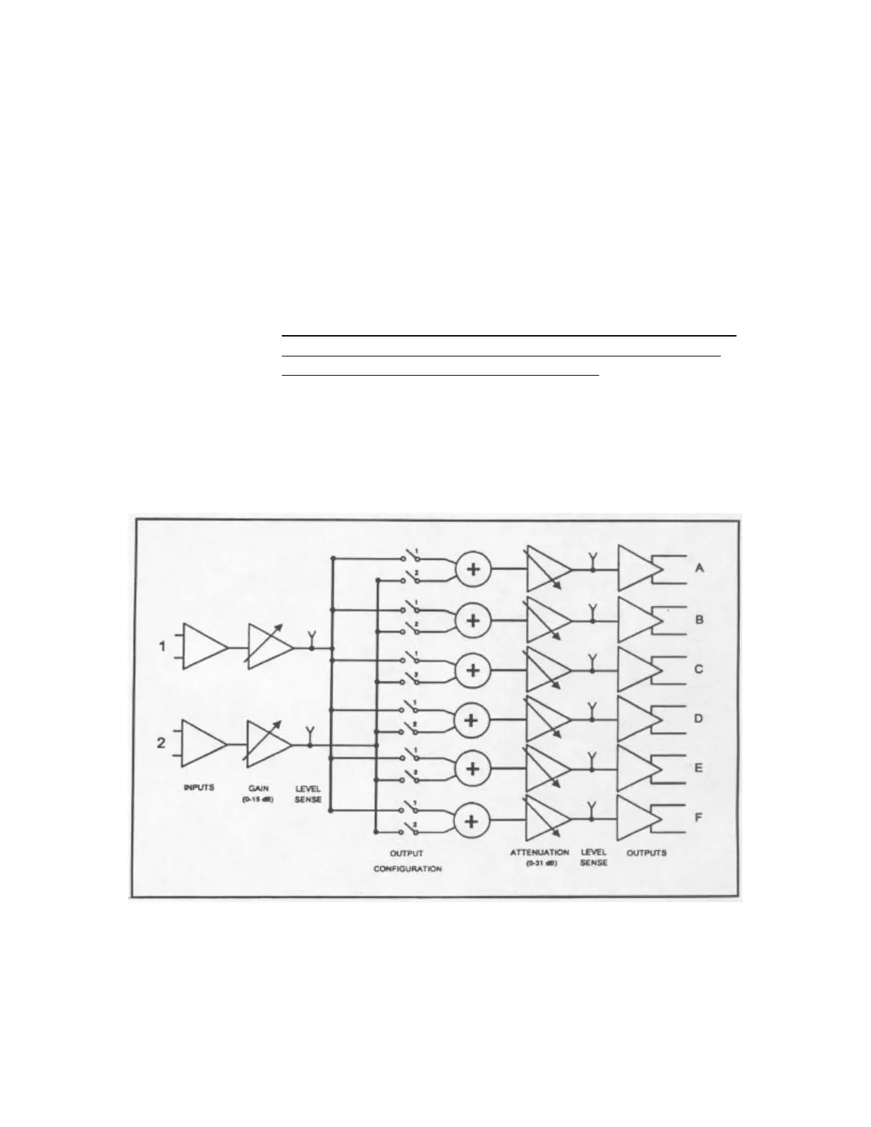
Figure 5 – Block Diagram