Do you have a question about the White Rodgers 1F56 Series and is the answer not in the manual?
Prevent electrical shock and equipment damage by disconnecting power before installation.
Do not use on circuits exceeding 30 volts to avoid damage and fire hazard.
Details on switch rating, heating/cooling current, and switch action.
Information on temperature range and differential settings.
Intended uses and systems for the thermostat, including limitations.
Guidelines for choosing the optimal location for thermostat placement.
Instructions for routing thermostat wires through walls and floors.
Specific wiring instructions for electric heat and two-transformer systems.
Instructions for single-stage heat pump system wiring and terminal use.
Steps for physically connecting the thermostat to its subbase.
General wiring overview showing terminal identification and hookup.
Wiring diagram for a single transformer heating/cooling system.
Wiring diagram for a two-transformer heating/cooling system.
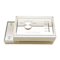
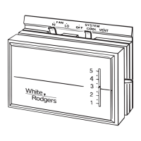
Explanation of how system and fan switches control operation.
This document provides comprehensive installation and operational instructions for the White-Rodgers 1F56 Series Low Voltage Heating/Cooling Thermostats. It emphasizes the importance of careful handling and adherence to safety precautions to prevent personal injury and property damage. The thermostat is designed to offer convenient and comfortable control over heating and cooling systems in residential and light commercial settings.
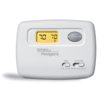
The White-Rodgers 1F56 Series thermostat is a low-voltage control device engineered to regulate indoor temperatures by managing heating and cooling equipment. Its core function is to sense the ambient room temperature and activate or deactivate the connected HVAC system to maintain a user-defined set point. The thermostat utilizes a sensitive spiral bimetal element for accurate temperature sensing, which is paired with an adjustable heating anticipator and a fixed cooling anticipator. These anticipators are crucial for optimizing system cycles, preventing temperature overshoots, and ensuring consistent comfort by predicting when the heating or cooling system needs to turn on or off slightly before the set point is reached.
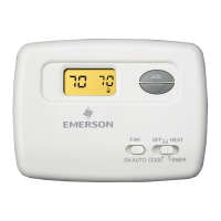
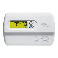
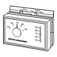
The device is equipped with a system switch that allows users to select between "COOL," "OFF," and "HEAT" modes, enabling seasonal control over the HVAC system. Additionally, a fan switch provides options for "AUTO" or "ON" operation. In "AUTO" mode, the fan cycles with the heating or cooling system, turning on only when the system is actively heating or cooling. In "ON" mode, the fan runs continuously, regardless of whether the heating or cooling system is active, which can be useful for improving air circulation or filtration.
The thermostat is designed for single-stage applications, meaning it can control one stage of heating and one stage of cooling. It is compatible with various system configurations, including standard heating and cooling systems, electric heating and cooling systems, single-stage heat pump systems, and two-transformer systems. It can also integrate with electronic air cleaners, humidifiers, and zone dampers, enhancing its versatility in a complete home comfort system.
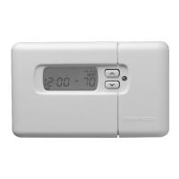
The 1F56 Series thermostat is designed for straightforward operation, making it user-friendly for homeowners. Key usage features include:
While the White-Rodgers 1F56 Series thermostat is designed for reliable operation with minimal user intervention, the manual outlines specific maintenance-related features and procedures to ensure its continued accuracy and performance:
In summary, the White-Rodgers 1F56 Series thermostat is a robust and user-friendly device designed for effective temperature control. Its features are geared towards providing consistent comfort, ease of operation, and the ability for users to maintain its accuracy over time through simple, well-documented adjustment procedures.
| Power Source | Battery (2 AA) |
|---|---|
| Stages | 1 Heat/1 Cool |
| Type | Non-programmable |
| Voltage | 24 VAC |
| Mounting | Wall |