EasyManua.ls Logo

White Rodgers 1F89-11 User Manual

White Rodgers 1F89-11
6 pages
To Next Page IconTo Next Page
Page #1 background imageLoading...
Page #1 background image
Printed in U.S.A.
FAILURE TO READ AND FOLLOW ALL INSTRUCTIONS CAREFULLY
BEFORE INSTALLING OR OPERATING THIS CONTROL COULD CAUSE
PERSONAL INJURY AND/OR PROPERTY DAMAGE.
DESCRIPTION
WHITE-RODGERS DIVISION
EMERSON ELECTRIC CO.
9797 REAVIS ROAD
ST. LOUIS, MISSOURI 63123-5398
WHITE-RODGERS
1F89-11
Non-Programmable Electronic Digital
Heat Pump Thermostat
INSTALLATION AND
OPERATION INSTRUCTIONS
PART NO. 37-5741A
Replaces 37-5612B
9636
Operator: Save these instructions for future use!
ELECTRICAL DATA
Electrical Rating:
20 to 30 VAC 50/60 Hz. or D.C.
0.05 to 1.5 Amps (Load per terminal)
1.5 Amps Maximum Total Load (All terminals
combined)
THERMAL DATA
Setpoint Temperature Range:
45°F to 90°F (7°C to 32°C)
Operating Ambient Temperature Range:
32°F to 105°F
Operating Humidity Range:
0 to 90% RH (non-condensing)
Shipping Temperature Range:
-40°F to 150°F
APPLICATIONS
For use with:
Heat pump systems with up to two stages heat,
one stage cool
DO NOT USE WITH:
Millivolt systems
Systems exceeding 30 VAC and 1.5 amps
3-wire zoned hydronic heating systems
SPECIFICATIONS
Your new White-Rodgers Digital Heat Pump Thermostat
uses the technology of a solid-state microcomputer to
provide precise temperature control. This thermostat of-
fers you the flexibility to set heating and cooling tempera-
tures that fit your needs.
Features:
Simultaneous heat and cool temperature storage
LCD continuously displays set point and room tem-
perature
°F/°C convertibility
Temperature range 45° to 90°F
Eight terminals for single or two-transformer systems
O/B terminal for heat pump systems
Armchair Demonstration Capability
CAUTION
!
To prevent electrical shock and/or equipment
damage disconnect electric power to system at
main fuse or circuit breaker box until installation
is complete.
Do not use on circuits exceeding specified volt-
age. Higher voltage will damage control and
could cause shock or fire hazard.
Do not short out terminals on gas valve or pri-
mary control to test. Short or incorrect wiring will
damage thermostat and could cause personal
injury and/or property damage.
WARNING
!
This thermostat is intended for use with a 24-volt system;
do not use this thermostat with a millivolt or line voltage
system. If in doubt about whether your wiring is millivolt,
line, or low voltage, have it inspected by a qualified
heating and air conditioning contractor or electrician.
Do not exceed the specification ratings.
All wiring must conform to local and national electrical
codes and ordinances.
This control is a precision instrument, and should be
handled carefully. Rough handling or distorting compo-
nents could cause the control to malfunction.
PRECAUTIONS
Question and Answer IconNeed help?

Do you have a question about the White Rodgers 1F89-11 and is the answer not in the manual?

White Rodgers 1F89-11 Specifications

General IconGeneral
TypeProgrammable Thermostat
Stages1 Heat / 1 Cool
Power SourceBattery (2 AA)
DisplayDigital
Voltage24V
BacklightYes

Summary

Description

Electrical Data

Electrical rating for the thermostat, including voltage and current limits.

Thermal Data

Temperature ranges for setpoint and operation.

Applications

Details on systems compatible with and not compatible with the thermostat.

Precautions

Caution

To prevent electrical shock and/or equipment damage disconnect electric power to system.

Warning

Do not use on circuits exceeding specified voltage. Higher voltage will damage control.

Installation

Remove Old Thermostat

Instructions for safely removing the existing thermostat from the wall.

Attach Thermostat Base to Wall

Steps for mounting the new thermostat base securely to the wall.

Non-Electric Heat Systems

Information on configuring the thermostat for non-electric auxiliary heat systems.

O/B Terminal Switch Selection

Guide for setting the O/B switch based on heat pump wiring.

Armchair Demonstration

How to test thermostat features before wall mounting using a battery.

Check Thermostat Operation

Fan Operation

Steps to verify the fan operates correctly in AUTO and ON modes.

Heating System

Procedure to test the heating system's response to temperature changes.

Cooling System

Procedure to test the cooling system's response to temperature changes.

Lockout Bypass Option

Compressor Short Term Cycle Protection

Explains the 5-minute compressor lockout for head pressure stabilization.

Operation

The Thermostat Base

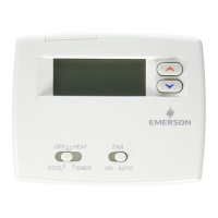
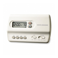
Details the location and operation of buttons and switches on the thermostat base.

The Display

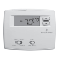
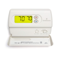
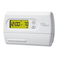
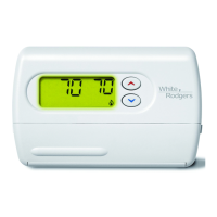
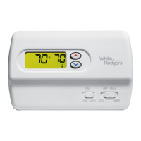
Explains the meaning of icons and text displayed on the thermostat screen.

Operating Features

Describes key features like temperature setpoint adjustment and F/C conversion.

Setting Your Thermostat

Instructions on how to set the system mode, temperature, and fan operation.

Related product manuals