1
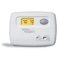
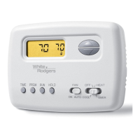
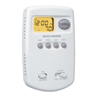
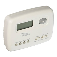
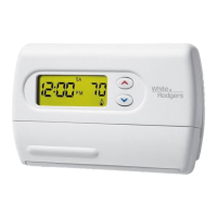
Blue 2” Heat Pump Thermostat
Heat Pump or Single Stage
Installation and Operating Instructions
Save these instructions for future use!
FAILURE TO READ AND FOLLOW ALL INSTRUCTIONS
CAREFULLY BEFORE INSTALLING OR OPERATING THIS
CONTROL COULD CAUSE PERSONAL INJURY AND/OR
PROPERTY DAMAGE.
APPLICATIONS
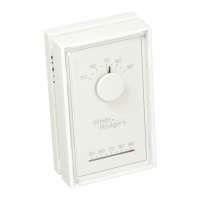
1F89-0211 Thermostat
Model Programming Choices
1F89-0211 Non-Programmable
SPECIFICATIONS
Electrical Rating:
Battery Power ................................................. mV to 30 VAC, 50/60 Hz or DC
Input-Hardwire ................................................ 20 to 30 VAC
Terminal Load ........................................................ 1.5 A per terminal, 2.5A maximum all terminals combined
Setpoint Range ...................................................... 45° to 90°F (7° to 32°C)
Differential (Single Stage) ...................................... Heat 0.8°F; Cool 1.2°F (adjustable)
Differential (Heat Pump) ........................................ Heat 1.2°F; Cool 1.2°F (adjustable)
Operating Ambient ................................................. 32° to +105°F (0° to +41°C)
Operating Humidity ................................................ 90% non-condensing max.
Shipping Temperature Range ................................ -40° to +150°F (-40° to +65°C)
Dimensions Thermostat ......................................... 3-3/4”H x 4-3/4”W x 1-1/2”D
PRECAUTIONS
To prevent electrical shock and/or equipment damage,
disconnect electric power to system at main fuse or
circuit breaker box until installation is complete.
CAUTION
!
Do not use on circuits exceeding specifi ed voltage.
Higher voltage will damage control and could cause
shock or fi re hazard.
Thermostat installation and all components of the
system shall conform to Class II (current limited)
circuits per the NEC code. Failure to do so could cause
a fi re hazard.
WARNING
!
PART NO. 37-6997C
Replaces 37-6997B
0932
www.white-rodgers.com
YOUR THERMOSTAT REPLACES
Description
Heat Pump (No Aux. or Emergency Heat) Yes
Heat Pump (with 1 Aux. or Emergency Heat Stage) Yes
Standard Heat & Cooling Systems Yes
Two Stage Heat & Two Stage Cool No
Standard Heat Only Systems Yes
Millivolt Heat Only Systems - Floor or Wall Furnaces Yes
Standard Central Air Conditioning Yes
Gas or Oil Heat Yes
Electric Furnace Yes
Hydronic (Hot Water) Zone Heat – 2 Wires Yes
Hydronic (Hot Water) Zone Heat – 3 Wires No
Index Page
Installation 2
Wiring Diagrams 3
Thermostat Quick Reference 4
Installer Confi guration Menu 4
Operation 6
Troubleshooting 7