Installation Instructions for
Heating & Air Conditioning
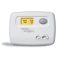
1F72
5/2 Day Programmable
Heat Pump Thermostat
CONTENTS
Preparations.................................................. 1
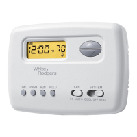
Thermostat Details ........................................ 1
Removing Old Thermostat .........................1-2
Mounting and Wiring ..................................2-3
Check Thermostat Operation .....................4-5
Programming your Thermostat ..................6-7
Specifications ................................................ 7
Troubleshooting .........................................7-8
PREPARATIONS
THERMOSTAT DETAILS
REMOVING OLD THERMOSTAT
Before removing wires from old thermostat’s switching subbase,
label each wire with the terminal designation it was removed from.
1. Remove Old Thermostat: A standard heat/cool thermostat
consists of three basic parts:
a. The cover, which may be either a snap-on or hinge type.
b. The base, which is removed by loosening all captive screws.
c. The switching subbase, which is removed by unscrewing
the mounting screws that hold it on the wall or adaptor plate.
2. Shut off electricity at the main fuse box until installation is
complete. Ensure that electrical power is disconnected.
3. Remove the front cover of the old thermostat. With wires still
attached, remove wall plate from the wall. If the old thermostat
has a wall mounting plate, remove the thermostat and the wall
mounting plate as an assembly.
4. Identify each wire attached to the old thermostat using the
labels enclosed with the new thermostat.
5. Disconnect the wires from the old thermostat one at a time. DO
NOT LET WIRES FALL BACK INTO THE WALL.
6. Install new thermostat using the following procedures.
To prevent electrical shock and/or equipment damage,
disconnect electrical power to the system at the main
fuse or circuit breaker until installation is complete.
CAUTION
!
Printed in U.S.A.
PART NO. 37-6498A
0342
WHITE-RODGERS
EMERSON ELECTRIC CO
ST. LOUIS, MISSOURI
www.white-rodgers.com
Failure to follow and read all instructions carefully
before installing or operating this control could cause
personal injury and/or property damage.
Assemble tools required as shown below.
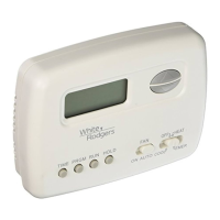
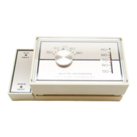
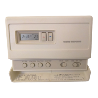
YOUR THERMOSTAT REPLACES
1
2
3
WIRE CUTTER/STRIPPER
Description
Heat Pump (No Aux or Emergency Heat) Yes
Heat Pump (with Aux or Emergency Heat) Yes
Standard Heat & Cooling Systems No
Standard Heat Only Systems No
Millivolt Heat Only Systems – Floor or Wall Furnaces No
Standard Central Air Conditioning No
Gas or Oil Heat No
Electric Furnace No
Hydronic (Hot Water) Zone Heat – 2 Wires No
Hydronic (Hot Water) Zone Heat – 3 Wires No
HAND OR POWER
DRILL WITH 3/16 INCH
DRILL BIT, IF NEEDED
FLAT BLADE SCREWDRIVER
SPIRIT LEVEL OR PLUMB BOB AND LINE OPTIONAL—
THERMOSTAT DOES NOT NEED TO BE LEVEL TO WORK PROPERLY
Figure 1. Thermostat base
W905
Clip for
Slow Cycle
W904
Clip for
Celsius
W903
Clip to
Disable
EMR
Feature
Mounting
hole
W906 for Emergency
Heat Second Stage
Fan Control
O/B
Terminal
Switches
Selection
Mounting
hole