Do not use on circuits exceeding specified voltage.
Higher voltage will damage control and could cause
shock or fire hazard.
Do not short out terminals on gas valve or primary
control to test. Short or incorrect wiring will damage
thermostat and could cause personal injury and/or
property damage.
Thermostat installation and all components of the
system shall conform to Class II (current limited)
circuits per the NEC code. Failure to do so could cause
a fire hazard.
FAILURE TO READ AND FOLLOW ALL INSTRUCTIONS CAREFULLY
BEFORE INSTALLING OR OPERATING THIS CONTROL COULD CAUSE
PERSONAL INJURY AND/OR PROPERTY DAMAGE.
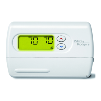
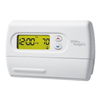
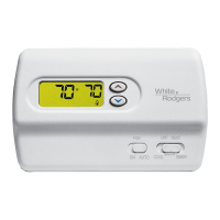
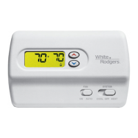
DESCRIPTION
SPECIFICATIONS
ELECTRICAL DATA
Electrical Rating:
20 to 30 VAC 50/60 Hz. or D.C.
0.05 to 1.0 Amps (Load per terminal)
1.5 Amps Maximum Total Load (All terminals combined)
THERMAL DATA
Setpoint Temperature Range:
45°F to 90°F (7°C to 32°C)
Operating Ambient Temperature Range:
32°F to 105°F
Operating Humidity Range:
0 to 90% RH (non-condensing)
Shipping Temperature Range:
-4°F to 149°F
APPLICATIONS
For use with the following Class II systems:
• Standard heat pump systems with electric, gas or oil
Aux heat with 24VAC Hot and Common available
• Single-stage heat pump systems with no Aux heat with
24VAC Hot and Common available
DO NOT USE WITH:
• Millivolt systems
• Systems exceeding 30 VAC and 1.5 amps
• 3-wire zoned hydronic heating systems
1F82-261
Programmable Electronic Digital
Heat Pump Thermostat
INSTALLATION AND
OPERATION INSTRUCTIONS
Printed in U.S.A.
PART NO. 37-6175D
Replaces 37-6175C
0225
PRECAUTIONS
This thermostat is intended for use with a low voltage NEC
Class II system. Do not use this thermostat with a line voltage
system. If in doubt about whether your wiring is millivolt, line, or
low voltage, have it inspected by a qualified heating and air
conditioning contractor or electrician.
Do not exceed the specification ratings.
All wiring must conform to local and national electrical codes
and ordinances.
This control is a precision instrument, and should be handled
carefully. Rough handling or distorting components could cause
the control to malfunction.
To prevent electrical shock and/or equipment dam-
age, disconnect electric power to system at main fuse
or circuit breaker box until installation is complete.
Operator: Save these instructions for future use!
WHITE-RODGERS
EMERSON ELECTRIC CO.
9797 REAVIS ROAD
ST. LOUIS, MISSOURI 63123-5398
www.white-rodgers.com
▲
! CAUTION
▲
! WARNING
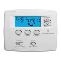
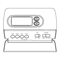
• LCD continuously displays set point, and alternately dis-
plays time and room temperature
• Continuous Backlit display option
• Temperature override until next program period
• Manual program override (HOLD temperature)
• Temporary HOLD
• °F/°C convertibility
• Temperature range 45° to 90°F
• R, C, Y, W2, G, O/B, E, and L terminals for single or two-
transformer systems
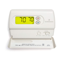
Your new White-Rodgers 5-Day/1-Day/1-Day Digital Thermo-
stat uses the technology of a solid-state microcomputer to
provide precise time/temperature control. This thermostat offers
you the flexibility to design heating and cooling programs that fit
your needs.
Features:
• Separate 5-day (weekday) and 1-day/1-day (Saturday/Sunday)
programming with four separate time/temperature periods per day
• Simultaneous heat and cool program storage
• Preprogrammed temperature control
• Optional battery back-up for AC power loss