Printed in U.S.A.
PART NO. 37-5456A
Replaces 37-1794 &
37-9517
9510
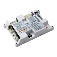
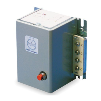
TYPE 668
Intermittent Ignition* – Non Recycling
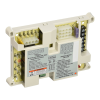
OIL BURNER CONTROL
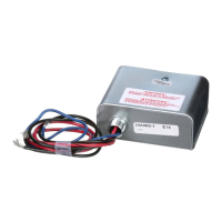
With Series 956 Flame Detector
INSTALLATION INSTRUCTIONS
Operator: Save these instructions for future use!
WHITE-RODGERS DIVISION
EMERSON ELECTRIC CO.
9797 REAVIS RD., ST. LOUIS, MO. 63123
(314) 577-1300, Fax (314) 577-1517
9999 HWY. 48, MARKHAM, ONT. L3P 3J3
(905) 475-4653, FAX (905) 475-4625
DESCRIPTION
FAILURE TO READ AND FOLLOW ALL INSTRUCTIONS CAREFULLY BEFORE
INSTALLING OR OPERATING THIS CONTROL COULD CAUSE PERSONAL
INJURY AND/OR PROPERTY DAMAGE.
The proper Location and Mounting of the primary oil
burner control panel on the burner and the flame detector
with respect to the oil flame shall be determined by the
furnace, boiler, or burner manufacturer.
If this control, supplied as part of a furnace, boiler or
burner, is wired to the equipment or if the manufacturer
of such equipment provides instructions for wiring this
* Formerly called constant ignition.
SPECIFICATIONS
Electrical Data
Input voltage: 668 120V. AC, 60Hz.
668H 220V. AC, 50/60Hz.
Maximum Load Current:
Oil Burner Motor (Orange Wire):
10 Amps F.L. 60 Amps L.R.
Ignition Transformer:
360VA (3.0 Amps)
Relay Voltage: 668 24 Volts AC, 60Hz.
668H 24 Volts AC, 50/60Hz
Room Thermostat:
Set adjustable heat anticipator at 0.4 Amps. For fixed
anticipation thermostats, use 0.35 to 0.45 Amp.
heater.
Safety Timing:
668, 668H-401 to 499: 45 seconds
668, 668H-501 to 599: 30 seconds
668, 668H-601 to 699: 15 seconds
INSTALLATION AND WIRING
control, then follow his recommendations. If no special
wiring instructions are given, then follow the electrical
connections shown on this diagram for a simple system.
For more complicated systems, especially for hot water
heating, consult the manufacturer of the heating plant for
full details of the desired sequence of control operation.
To prevent electrical shock and/or equipment
damage, disconnect electric power to system, at
main fuse or circuit breaker box, until installation
is complete.
Do not use on circuits exceeding specified volt-
ages. Higher voltages will damage control and
could cause shock or fire hazard.
If in doubt about whether your wiring is millivolt, line, or
low voltage, have it inspected by a qualified heating and
air conditioning contractor, electrician, or someone famil-
iar with basic electricity and wiring.
Do not exceed the specification ratings.
All wiring must conform to local and national electrical
codes and ordinances.
This control is a precision instrument, and should be
handled carefully. Rough handling or distorting compo-
nents could cause the control to malfunction.
CAUTION
!
PRECAUTIONS
WHITE-RODGERS
The type 668 Oil Burner Control provides safe operation
of oil burners on heating plants where ignition during the
entire burner cycle is desired.
The 668 is used with the 956 Flame Detector