EasyManua.ls Logo

White Rodgers 21M51U-843 User Manual

White Rodgers 21M51U-843
3 pages
To Next Page IconTo Next Page
Page #1 background imageLoading...
Page #1 background image
21M51U-843 Replaces:
18M3401 50M61-495
20300001 50M61-843
20300003 83L9301
21M51U-843 CNT03077
46M9901 CNT6424
50M51-242 D344301P01
50M51-495 PCBBF120S
50M61-120 PCBBF125
50M61-288 X13650839010
50M61-289
CROSS REFERENCE
21M51U-843 Kit
Includes:
•Module
•HotRod
Ignitor Kit
Model
Number Pre-Purge
Ignitor
Warm-Up Retries
Heat
Delay to
Fan ON
Heat Delay
to Fan OFF
Cool
Delay to
Fan ON
Cool
Delay to
Fan OFF
Automatic
Reset
Time
21M51U-843 15 17 2 45 90/120/150/180 5 60 60 minutes
?
PAGES
179–180
21M51U-843 UNIVERSAL INTEGRATED HSI
FURNACE CONTROL KIT
Replaces White-Rodgers 50M51-242 and 50M61-XXX's Two-Stage
HSI Systems with 80V or 120V Ignitors
FEATURES
•120VAC3-speedPSC(PermanentSplitCapacitor)circulatoroutput,two-speed
inducer output, two-stage gas valve output.
•Pushbuttonfaulthistoryretrieval.
•FurnacestatusLED–tri-color(green,redandamber).
•Heatfanoffdelay(dipswitchselectable),fanondelayforcooling.
•Autosecondstagedelay(dipswitchselectable).
•120VAChumidieroutput/120VACelectronicaircleaneroutput.
SPECIFICATIONS
Electrical Rating:
Input Voltage.................... 24 VAC, 60 Hz (Class II transformer required)
Nom. Input Current @ 24 VAC ...... 530mA+MV
Relay Load Ratings:
Gas Valve Relays ................ 1.5 amps @ 24 VAC, 60 Hz
Inducer Relays . . . . . . . . . . . . . . . . . . 2.2 FLA – 3.5 LRA @ 120 VAC
Circulator Relays ................ 14.5 FLA – 25.0 LRA @ 120 VAC
HumidierLoad ................. 1.0 amp max. @ 120 VAC
Electronic Air Cleaner Load ........ 1.0 amp max. @ 120 VAC
Ignitor Relay .................... 4.0 amps max. @ 132 VAC, 60 Hz
Flame Current Requirements:
Minimumcurrenttoinsureamedetection 0.3 µa DC*
Maximum current for non-detection .. 0.1 µa DC*
Maximumallowableleakageresistance100Mohms
*Measured with a DC microameter in the flame probe lead
Operating Temperature Range...... -40
o
to 175
o
F (-40 to 80
o
C)
Humidity Range ................. 5% to 93% relative humidity (non-condensing)
Flame Failure Response Time . . . . . . 2.0 sec. max. @ 60Hz
TECHNICAL HELP
Wiring Diagram/Operation .............. See pages 179–180
TWO-STAGE
INTEGRATED 3-SPEED (PSC)
HSI FURNACE CONTROL
UNIVERSAL
REPLACEMENT
www.white-rodgers.com
45
HEATING
Question and Answer IconNeed help?

Do you have a question about the White Rodgers 21M51U-843 and is the answer not in the manual?

White Rodgers 21M51U-843 Specifications

General IconGeneral
TypeIntegrated Furnace Control
Ignition TypeHot Surface Ignition
Voltage24 VAC
Operating Temperature Range-40°F to 175°F (-40°C to 80°C)
CertificationUL Recognized
Compatible Furnace TypesGas

Summary

21M51U-843 Universal Integrated HSI Furnace Control Kit

Features

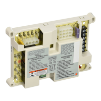
Highlights key capabilities including circulator output, inducer output, gas valve output, fault history, and status LED.

Specifications

Details electrical ratings, relay load ratings, flame current requirements, and operating environmental parameters.

Technical Help

Provides access to wiring diagrams, operation guides, and cross-references for technical assistance.

Cross Reference

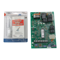
Lists compatible replacement part numbers, including specific White-Rodgers models.

21M51U-843 Wiring and Configuration

Typical Wiring Diagram

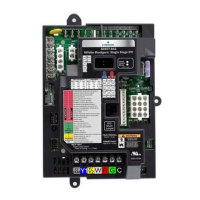
Illustrates the typical wiring connections for the 50M51-843 furnace control, including component identification.

Wiring Legend

Explains the symbols and abbreviations used in the wiring diagram for clarity.

Diagnostic Table

Error/Condition Codes

Lists diagnostic error codes, their corresponding LED flashes, and troubleshooting comments for specific failures.

Diagnostic Features

Explains how the control monitors system operation and indicates failures via LED flash sequences.

Last Fault Mode

Describes the procedure to retrieve stored fault codes using the 'LAST ERROR' button.

Related product manuals