To prevent electrical shock and/or equipment
damage, disconnect electric power to system at
main fuse or circuit breaker box until installation
is complete.
Label all wires prior to disconnection when ser-
vicing controls. Wiring errors can cause improper
and dangerous operation.
Following installation or replacement, follow
appliance manufacturers’ recommended instal-
lation/service instructions to insure proper op-
eration.
PART NO. 37-1558B
Replaces 37-1558-1
9714
Printed in U.S.A.
FAILURE TO READ AND FOLLOW ALL INSTRUCTIONS CAREFULLY
BEFORE INSTALLING OR OPERATING THIS CONTROL COULD CAUSE
PERSONAL INJURY AND/OR PROPERTY DAMAGE.
DESCRIPTION
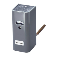
WHITE-RODGERS
5D51-35, -78 & -90
Fan & Limit Control
INSTALLATION INSTRUCTIONS
This fan and limit control combines, in one enclosure, a
fan switch with an adjustable differential which operates
the blower in a forced warm air furnace and a limit switch
with a fixed differential which automatically shuts off the
burner if the furnace temperature exceeds a predeter-
mined high point.
Operator: Save these instructions for future use!
PRECAUTIONS
THIS CONTROL MUST BE INSTALLED BY A QUALI-
FIED INSTALLER.
All wiring must conform to local and national electrical
codes and ordinances.
This control is a precision instrument, and should be
handled carefully. Rough handling or distorting compo-
nents could cause the control to malfunction.
This control has been accurately calibrated at the factory.
Any attempt to re-calibrate this control will void the White-
Rodgers warranty.
Do not use on circuits exceeding specified volt-
ages. Higher voltages will damage control and
could cause shock or fire hazard.
If in doubt about whether your wiring is millivolt,
low or line voltage, have it inspected by a quali-
fied heating and air conditioning contractor or a
licensed electrician.
CAUTION
!
A summer fan switch is incorporated in this control to
provide a convenient method for manual operation of the
fan for air circulation during the summer.
WARNING
!
INSTALLATION
Removing Cover
To remove cover from control, grasp cover at top and
bottom and pull outward. Grasping the cover by its sides
will make removal more difficult.
Location
1. The bimetal element should not be too close to any
hot surfaces of the heat exchanger. The element
should always be at least 3“ away from any hot
surfaces unless the position has been determined
acceptable by the furnace manufacturer.
2. If this is a new application, please consult the original
equipment manufacturer for proper location.
Mounting, For Flush Mounting (Vertical or
Sloping Surface)
1. Insert the element tube into the bonnet and attach
control case with #10 screws. (Two screws, diago-
nally located, are sufficient.)
2. Replace control cover after wiring and making any
adjustments to the settings.
WHITE-RODGERS DIVISION
EMERSON ELECTRIC CO.
9797 REAVIS RD., ST. LOUIS, MO. 63123-5398
(314) 577-1300, FAX (314) 577-1517
9999 HWY. 48, MARKHAM, ONT. L3P 3J3
(905) 475-4653, FAX (905) 475-4625