EasyManua.ls Logo

White Rodgers 50X57-843 User Manual

White Rodgers 50X57-843
20 pages
To Next Page IconTo Next Page
Page #1 background imageLoading...
Page #1 background image
FAILURE TO READ AND FOLLOW ALL INSTRUCTIONS CAREFULLY
BEFORE INSTALLING OR OPERATING THIS CONTROL COULD CAUSE
PERSONAL INJURY AND/OR PROPERTY DAMAGE.
PARTS INCLUDED
50X57-843 Integrated Furnace Control
2 - Harness Assemblies for Lennox Applications
1 - Rollout Shunt Jumper for Trane Applications
1 - Motor Common Adapter Wire for Trane Applications
4 - Plastic Mounting Standoffs and 1 – Bumper Stub
3 - ½” Sheet Metal Mounting Screws
2 – Wire Ties
Installation Instructions
DESCRIPTION
SPECIFICATIONS
ELECTRICAL RATINGS:
Input Voltage: 25 VAC, 50/60 Hz
Max Input Current: 0.8 A @ 25 VAC
Relay Load Ratings:
Gas Valve: 1.5 A 0.6 PF @ 30 VAC
Ignitor Relay: 1.2 A @ 120 VAC
Inducer Relay: 2.8 A @ 120 VAC
Circulator Relays: 12.0 mA @ 30 VAC
Humidifier Load: 1.0 A @ 120 VAC
0.5 A @ 24 VAC
Electronic Air Cleaner: 1.0 A @ 120 VAC
Flame Current Requirements:
Min current to ensure flame detection: 0.31 μA DC*
Max current for non-detection: 0.1 μA DC
Max allowable leakage resistance: 100 M ohms
* Measuring with a DC voltmeter (1VDC = 1 μA)
Flame Failure Response Time: 2.5 seconds maximum
OPERATING TEMPERATURE RANGE:
-40° to 176°F (-40° to 80°C)
HUMIDITY RANGE:
5 to 95% relative humidity (non-condensing)
AGENCY APPROVALS:
UL
GASES APPROVED: Natural, Manufactured, Mixed,
Liquid Petroleum, and LP Gas Air Mixtures
PART NO. 37-7672001
1815
50X57-843 for ECMx Furnaces
Universal Integrated Single Stage
120V Hot Surface Ignition Control Kit
INSTALLATION INSTRUCTIONS
The 50X57-843 is an aftermarket universal replacement
control kit for single stage furnaces with ECMx constant
torque blower motors.
CAUTION
!
Risk of Electric Shock.
Disconnect electric power
to system until installation
is complete. Do not use on
circuit exceeding specified
voltage. Higher voltage will
damage control and could
cause shock or fire hazard.
This control is not intended
for use in locations where
it may come in contact with
water.
May cause flame rollout.
Shut off main gas to heat-
ing system until installa-
tion is complete.
TWINNING: 50X57-843 can be twinned. Both control
boards must be from the same manufacturer for proper
functionality.
INSTALLER MUST READ
SPECIAL REPLACEMENT
INSTRUCTIONS FOR CARRIER,
TRANE AND LENNOX ON
PAGE 2
white-rodgers.com
emerson.com
Question and Answer IconNeed help?

Do you have a question about the White Rodgers 50X57-843 and is the answer not in the manual?

White Rodgers 50X57-843 Specifications

General IconGeneral
TypeIntegrated Furnace Control
Voltage24V AC
ProgrammableNo
PrepurgeYes
Ignition RetryYes
Flame SenseYes
StagesSingle Stage
BacklightNo
Ignition TypeDirect Spark Ignition
Replaces50A55-843
CompatibilityFurnaces

Summary

Parts Included

Description

Specifications

Electrical Ratings and Requirements

Comprehensive electrical specifications including input voltage, load ratings, flame current, and operating ranges.

Special Replacement Instructions

Carrier/ICP Transformer Secondary Hookup

Details transformer secondary wiring for Carrier/ICP furnaces.

Trane/American Standard Rollout Shunt and Ignitor Update

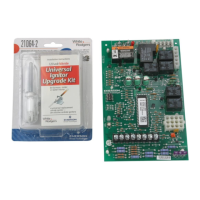
Instructions for installing rollout shunt jumpers and updating ignitors for Trane/American Standard furnaces.

Lennox Adapter Harnesses and Flame Sense Connection

Explains the use of adapter harnesses and flame sense connections for Lennox furnaces.

Installation

Mounting and Wiring Procedures

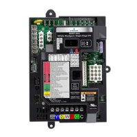
General guidelines for mounting and wiring the control unit according to codes.

Mounting Options

Describes the three available mounting methods for the control unit.

Dipswitch Setup

Configuration of dipswitches for heat off delay and fan speed settings.

Self-Test Procedure

Procedure for initiating and understanding the control's self-test mode.

Wiring Diagram and Connections

Connector Pinouts

Details pin configurations for various connectors including inducer/ignitor and main harnesses for different furnace types.

Operation

Heat Mode Operation

Describes the operational sequence and timing for the heat mode.

Cool Mode Delays

Explains blower on and off delays for cooling operation and dehumidification.

Dehumidification Function

Details how the control handles dehumidification calls and blower speed adjustments.

Heat Pump Operation

Outlines the operation of the control in heat pump mode.

Fan Only Operation

Describes the blower operation for a fan-only demand.

Troubleshooting, Fault and Status Codes

Stored Fault Codes

Lists fault codes stored in memory, indicating system errors and their conditions.

Non-Stored Fault Codes

Lists fault codes not stored in memory, related to ongoing system status or field tests.

Fault Recall Procedure

Instructions on how to recall stored fault codes from the control's memory.

Fault Code Reset Procedure

Procedure for resetting fault codes and understanding control reset mechanisms.

Related product manuals