EasyManua.ls Logo

White Rodgers 50A55-843 User Manual

White Rodgers 50A55-843
8 pages
To Next Page IconTo Next Page
Page #1 background imageLoading...
Page #1 background image
FIRE HAZARD
Do not exceed the specified voltage.
Protect the control from direct contact with water
(dripping, spraying, rain, etc.).
If the control has been in direct contact with water,
replace the control.
Label all wires before disconnection when servic-
ing controls. Wiring errors can cause improper
and dangerous operation.
Route and secure wiring away from flame.
SHOCK HAZARD
Disconnect electric power before servicing .
Ensure proper earth grounding of appliance.
Ensure proper connection of line neutral and line
hot wires.
EXPLOSION HAZARD
Shut off main gas to appliance until installation is
complete.
Printed in U.S.A.
50A55-843
Universal Integrated Furnace Control
FAILURE TO READ AND FOLLOW ALL INSTRUCTIONS CAREFULLY BEFORE
INSTALLING OR OPERATING THIS CONTROL COULD CAUSE PERSONAL
INJURY AND/OR PROPERTY DAMAGE.
DESCRIPTION
Operator: Save these instructions for future use!
INSTALLATION INSTRUCTIONS
WHITE-RODGERS
EMERSON ELECTRIC CO.
9797 REAVIS ROAD
ST. LOUIS, MISSOURI 63123-5398
www.white-rodgers.com
The 50A55-843 is an automatic gas interrupted ignition control
that employs a microprocessor to continually monitor, analyze,
and control the proper operation of the gas burner, inducer, and
fan.
Signals interpreted during continual surveillance of the thermo-
stat and flame sensing element initiate automatic ignition of the
burner, sensing of the flame, and system shut-off during normal
operation.
PRECAUTIONS
PART NO. 37-6265F
Replaces 37-6265E
0327
Installation should be done by a qualified heating and air
conditioning contractor or licensed electrician.
If in doubt about whether your wiring is millivolt, line, or low
voltage, have it inspected by a qualified heating and air condi-
tioning contractor or licensed electrician.
Do not exceed the specification ratings.
All wiring must conform to local and national electrical codes and
ordinances.
This control is a precision instrument, and should be handled
carefully. Rough handling or distorting components could cause
the control to malfunction.
Following installation or replacement, follow manufacturer’s
recommended installation/service instructions to ensure proper
operation.
CONTENTS
Description ......................................................... 1
Precautions ........................................................ 1
Specifications..................................................... 2
Installation.......................................................... 3
Mounting & Wiring
Operation ........................................................... 6
Mounting Hole Template.....................................8
These controls incorporate system fault analysis for quick gas
flow shut-off, coupled with automatic ignition retry upon sensing
a fault correction.
WARNING
Failure to comply with the following
warnings could result in personal injury
or property damage.
CAUTION
Do not short out terminals on gas valve or primary
control. Short or incorrect wiring may damage the
thermostat.

Other manuals for White Rodgers 50A55-843

Question and Answer IconNeed help?

Do you have a question about the White Rodgers 50A55-843 and is the answer not in the manual?

White Rodgers 50A55-843 Specifications

General IconGeneral
Voltage24V AC
Switch ActionSPST
MountingSurface mount
MaterialPlastic housing
CompatibilitySingle Stage Furnaces
FeaturesMicroprocessor-based
Operating Temperature-40°F to 175°F (-40°C to 79°C)
Voltage Rating24 VAC
Fan Control RangeAdjustable
TerminalsScrew terminals

Summary

Product Description

Safety Precautions and Warnings

General Safety Warnings

Details fire, shock, and explosion hazards requiring strict adherence to safety protocols.

Wiring and Component Cautions

Warns against shorting terminals or incorrect wiring, which can damage the thermostat.

Technical Specifications

Electrical Ratings

Details input voltage, max current, and relay load ratings for the control.

Operating Temperature Range

Specifies the acceptable operating temperature range for the control.

Humidity Range

Defines the acceptable relative humidity range for the control.

Timing Specifications

Lists various timing parameters for the control's operation cycles.

Installation Guide

Mounting and Wiring Procedures

Provides guidance on securing the control and connecting system wiring according to codes.

Trane Furnace Twinning

Specific jumper wire requirement for Trane furnaces to ensure proper twinning.

System Wiring Diagram

System Wiring Table

50A55 Terminal Connections

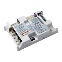
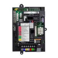
Details the terminal types and their system component connections for the 50A55 control.

Operational Modes and Settings

Option Switch Configuration

Explains how to set option switches to configure delay periods for fan operation.

Heat Mode Operation

Describes the heating sequence, ignitor warm-up, flame detection, and fan control.

Cool Mode Operation

Details the cooling sequence, including compressor and fan activation and deactivation.

Manual Fan Operation

Explains how to operate the circulator fan manually using the thermostat fan switch.

Twinning Interface

Twinning Enablement Procedure

Step-by-step instructions for connecting two 50A55-843 controls for twinning applications.

System Lockout and Diagnostics

System Lockout Features

Explains system lockout conditions and how to reset the control after a lockout.

Diagnostic Features and Error Codes

Describes failure codes indicated by the LED, helping to diagnose system issues.

Mounting Hole Template

Related product manuals