PETS-2 Crossing Telephone System
QUICKFIX INSTALLATION HANDBOOK
Page 15 of 40
Issue 2
13/12/99
15
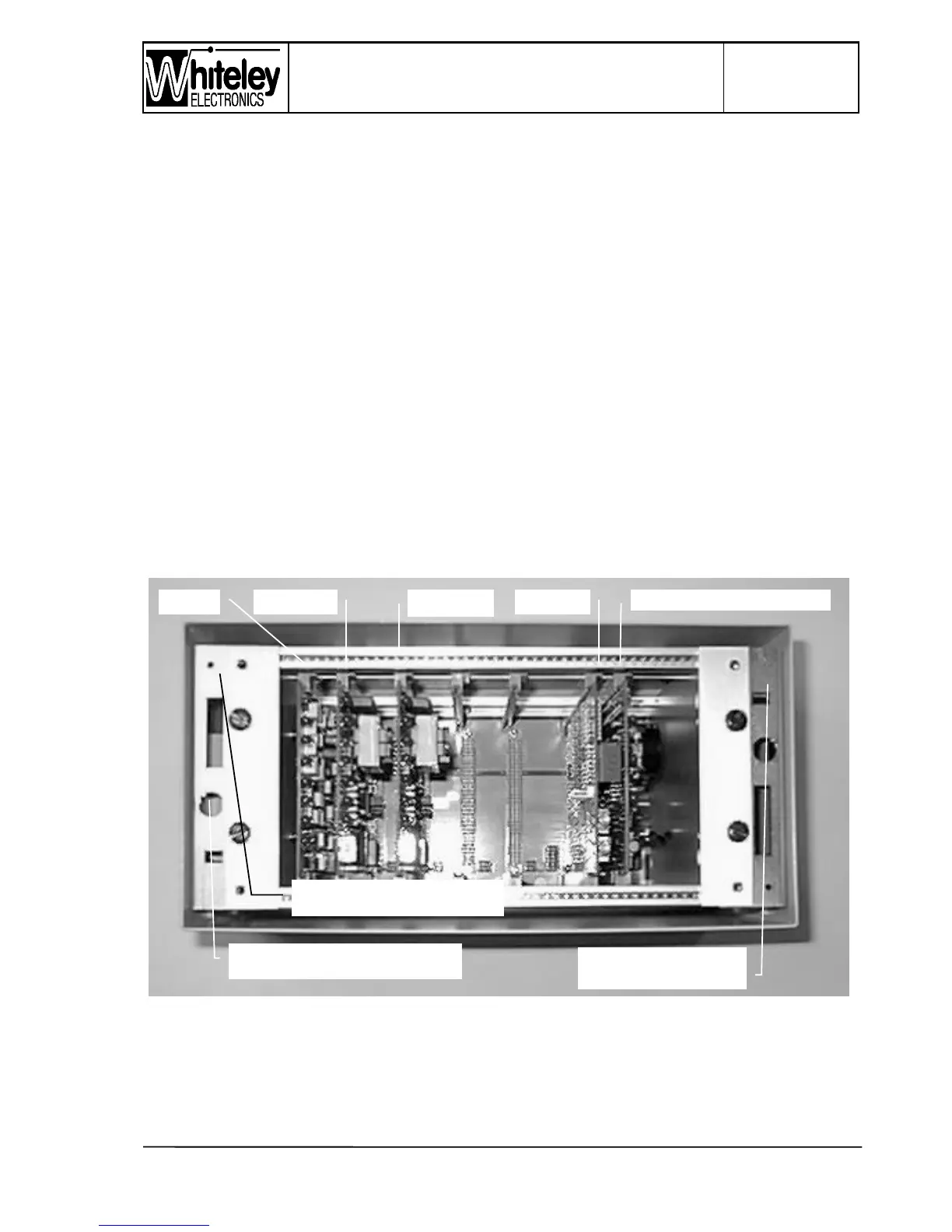
4.3.4 Item 4 - Right hand access plate
Photograph (Fig. 2) does not show the right hand side of the case, consequently Item 4 is
not identified. The right hand access plate is equipped with a series of 20mm knockouts.
This plate is not usually required for standard installations. It has been retained in PETS 2
to allow access to the right hand side of the frame and the motherboard.
4.3.5 Item 5 - Front panel
On the Level Crossing Unit the front panel takes the form of a metal tray with turned up
edges. Around the inside edge a strip of foam rubber sealing material is fitted, when the
front panel is fitted the seal is compressed by the edge of the case.
The front panel label allows all of the LED’s within to be visible, including the seven
segment Fault Code display. It is necessary to remove the front panel, by means of the four
fixing screws, to access the ‘Interrogate’ button to review multiple alarms. Removal of the
front panel will reveal the RESET button (immediately beneath the seven segment display).
The Interrogate button is beneath the RESET button.
4.4 Inside the case
Figure 3 - Photograph of the Card frame
Item 11
 Loading...