Page 30 of 40
Issue 2
13/12/99
PETS-2 Crossing Telephone System
QUICKFIX INSTALLATION HANDBOOK
30
# = these line circuits are not equipped on standard units.
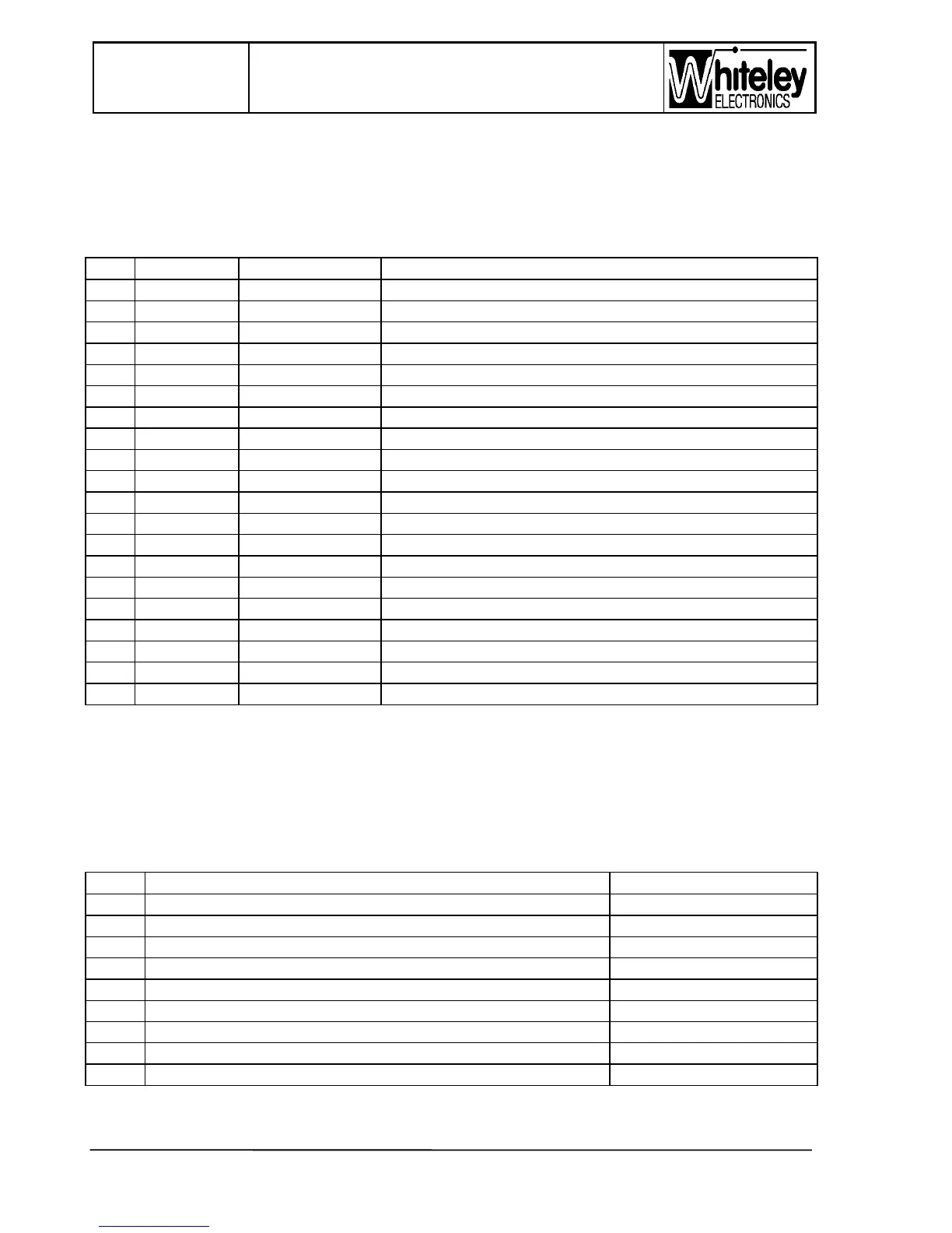
BLOCK 3 - the upper block (pair1 to the left)
NOTE: CONNECTIONS TO THIS BLOCK ARE ISOLATED FROM THE REST OF THE
SYSTEM - DO NOT JUMPER FROM BLOCK 3 TO THE OTHER BLOCKS.
Pair Signalbox Level Crossing Description
1a NC NC Spare
1b NC NC Spare
2a NC NC Spare
2b NC NC Spare
3a T4 (P) NA Block switching 4 wire (intermediate SB only)
3b T4 (O) NA Block switching 4 wire (intermediate SB only)
4a T4 (N) T4 (N) Four wire transmission Rx cct. Leg a
4b T4 (M) T4 (M) Four wire transmission Rx cct. Leg b
5a T3 (L) NA Block switching 4 wire (intermediate SB only)
5b T3 (K) NA Block switching 4 wire (intermediate SB only)
6a T3 (J) T3 (J) Four wire transmission Tx cct. Leg a
6b T3 (I) T3 (I) Four wire transmission Tx cct. Leg b
7a NA NA T2 relay ‘normally closed’ contact
7b NA NA T2 relay ‘normally closed’contact
8a T2 (F) NA Block switching 2 wire (intermediate SB only)
8b T2 (E) NA Block switching 2 wire (intermediate SB only)
9a T1 (D) NA Block switching 2 wire (intermediate SB only)
9b T1 (C) NA Block switching 2 wire (intermediate SB only)
10a T1 (B) T1 (B) Two wire transmission cct. leg a
10b T1 (A) T1 (A) Two wire transmission cct. leg b
5.8.1 Power supply
Power supply wiring descriptions are common to both Signal Box and level Crossing units.
Power supply connections are through the 9 pin (male) ‘D’ connector on the left hand side
of the case. The ‘D’ connector wiring is in accordance with the following table:
Pin Function Wire/ colour
1 Battery/ supply -ve (negative) -24V to 55V dc nominal 0.5mm/ 0.6mm, Pair 1a
2NC
3NC
4NC
5 Battery/ supply +ve 0.5mm/ 0.6mm, Pair 1b
6 Battery/ supply -ve -24V to 55V dc nominal 0.5mm/ 0.6mm, Pair 2a
7 Alarm - 0.5mm/ 0.6mm, Pair 3b
8 Alarm + 0.5mm/ 0.6mm, Pair 3a
9 Battery/ supply +ve 0.5mm/ 0.6mm, Pair 2b
 Loading...