Page 37 2016 Edition 1
WHYTE Service Manual
7.2.2: SRAM Maxle 142mm System
Reference figures 23 & 25. Loosely assemble all the parts as shown, making sure the Screws
(1) & (5) are correctly positioned, be very careful not to cross-thread these, on their
way in. Insert the rear wheel and the SRAM Maxle, as per the SRAM User Manual 95-4315-
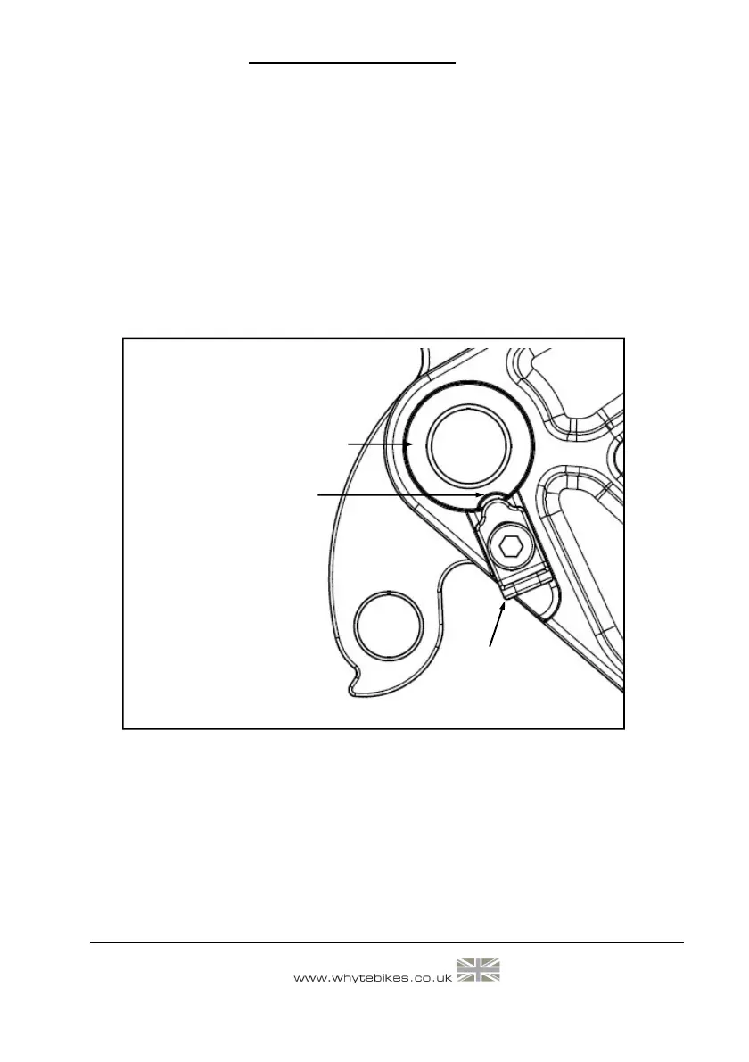
004-000. Whilst tightening the SRAM Maxle, make sure the nose of the Adjusting Clamp (2) is
aligned with the single slot in the Axle Nut (4), reference figure 25. Having tightened the
SRAM Maxle, slide the Clamp (2) upwards to engage it into the slot in the Axle Nut (4). Using
the Torque Wrench, tighten the Screws (1) & (5) to the correct torque as specified in Section
8.0.
DO NOT OVERTIGHTEN, since the threads of the Screws (1) & (5) are very small. Finally, if
necessary, adjust the SRAM Maxle Rear Axle as per the SRAM User Manual 95-4315-004-000.
Figure 25: Whyte Dropout Assembly -
Adjustment Clamp Alignment
(SRAM Maxle)
Align Nose of Clamp (2)
with Slot in Axle Nut (4)
4
2