Page 43 2016 Edition 1
into the seat tube and simultaneously pull
the hose through the frame.
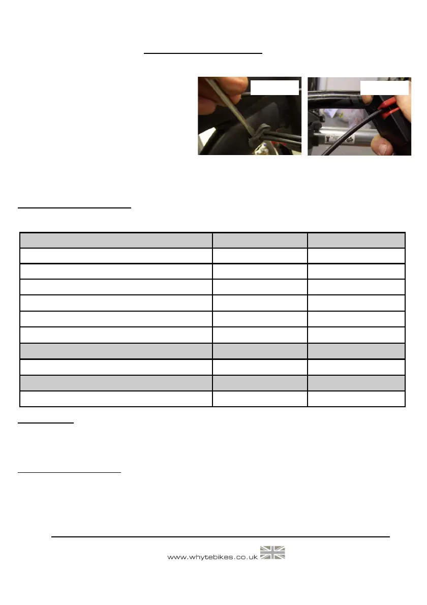
Reference figure 58. Insert all three rub-
ber grommets into the frame slots. Use a
small screwdriver with care not to split the
rubber.
Reference figure 59. Cut the hose to length and follow the product manufacturer’s instructions
to re-assemble and bleed the hydraulic system.
10.0: TORQUE SETTINGS
Torque explained: If no suitable Torque Wrench is available a Torque of 5 lbf.ft can be obtained by applying
a force of 5lb, with a Spring Balance, to the end of a spanner, 1 Foot in length.
IMPORTANT: For all other torque settings, refer to the specific manufacturers information
bundled with this manual, or alternatively, refer to the specific manufacturers website for fur-
ther information.
11.0: OWNER’S NOTES
Rear Suspension Nm lbs.ft
15 A/F M22 & M24 Link Outer Bearing Caps 2.3 (Min) - 2.7 (Max) 1.7 (Min) - 2.0 (Max)
M8 Flanged Nut 16.1 (Min) - 19.9 (Max) 11.9 (Min) - 14.7 (Max)
M6 Countersunk Cap Screw
8.5 (Min) - 10.5 (Max) 6.3 (Min) - 7.7 (Max)
M8 x 23 long Flanged Screw (T25 Torx®)
13.5 (Min) - 16.5 (Max) 10.0 (Min) - 12.2 (Max)
M5 Socket-head Cap Screw (T-25 Torx®)
5.0 (Min) - 6.0 (Max) 3.7 (Min) - 4.4 (Max)
Rear Dropout Assemblies
M4 Screws
4.2 (Min) - 4.6 (Max) 3.1 (Min) - 3.4 (Max)
M12 Flanged Screw & Flanged Nut 16.1 (Min) - 19.9 (Max) 11.9 (Min) - 14.7 (Max)
Seat Post Clamp
M6 Cap Screw 10 (Min) - 12 (Max) 7.4 (Min) - 9.2 (Max)
WHYTE Service Manual
Figure 58
Figure 59