3. Specications
Pressure limitation
Steady: 3/4 x full scale value
Fluctuating: 2/3 x full scale value
Short time: Full scale value
Temperature eect
When the temperature of the measuring system deviates from the reference temperature (+20 °C): max.
±0.4 %/10 K of full scale value
IP Ingress protection
1)
(per IEC/EN 60529)
IP65, IP66
For further specications see WIKA data sheet PM 02.02, PM 02.04, PM 02.12 or PM 02.24 and the order
documentation.
1) For general use, no ATEX requirement
4. Design and function
Description
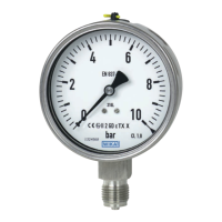
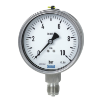
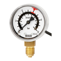
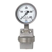
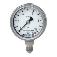
Nominal size 63 mm
The instruments measure the pressure by means of resilient bourdon tube pressure elements
The measuring characteristics are in accordance with the EN 837-1 standard
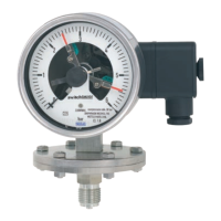
In accordance with the EN 837-1 standard, pressure gauges with “S3” marking are safety pressure
gauges whose enclosing and pressurised components are designed with a solid bae wall. Models
with “S3” marking are 232.30, 233.30, 262.30, 263.30. Model PG23CP is optionally available as an
“S3” variant.
Scope of delivery
Cross-check scope of delivery with delivery note.
5. Transport, packaging and storage
5.1 Transport
Check pressure gauge for any damage that may have been caused by transport.
Obvious damage must be reported immediately.
5.2 Packaging
Do not remove packaging until just before mounting.
Keep the packaging as it will provide optimum protection during transport (e.g. change in installation site,
sending for repair).
5.3 Storage
Permissible storage temperature
-40 ... +70 °C
6. Commissioning, operation
Mechanical connection
In accordance with the general technical regulations for pressure gauges (e.g. EN 837-2 “Selection and
installation recommendations for pressure gauges”).
Pressure gauges must be grounded via the process connection. This is why electrically conductive
sealings should be used at the process connection. Alternatively, take other measures for grounding.
When screwing gauges in, the force required for this must not be applied through the case, but rather
through the spanner ats (using a suitable tool) provided for this purpose on the square shaft of standard
connections.
For parallel threads, use at gaskets, lens-type sealing rings or WIKA prole sealings at the sealing face
. With tapered threads (e.g. NPT threads), sealing is made in the threads
using suitable sealing
material (EN 837-2).
The torque depends on the seal used. Connecting the gauge using a clamp socket or a union nut is
recommended, so that it is easier to orientate the gauge correctly.
When a blow-out device is tted to a pressure gauge, it must be protected against being blocked by
debris and dirt.
Requirements for the installation point
If the measuring point is not suciently stable a measuring instrument support such as a bracket or
ange should be used for fastening (possibly via a exible capillary). If vibrations cannot be avoided by
taking suitable measures during installation, liquid-lled instruments should be used. Instruments must be
protected against coarse dirt and wide uctuations in ambient temperature.
Installation
Nominal position per EN 837-1 / 9.6.7 Figure 9: 90° ( ⊥ )
Process connection lower mount (LM) or back mount (BM)
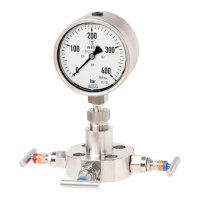
After mounting, set the compensating valve (if available) from CLOSE to OPEN. The
version of the vent valve depends on the model and can deviate from the illustration!
For outdoor applications, the selected installation location has to be suitable for the
specied ingress protection, so that the pressure gauge is not exposed to impermissible weather
conditions.
In order to avoid any additional heating, the instruments must not be exposed to direct solar irradiation
while in operation!
To ensure that the pressure can be safely vented in the case of failure instruments with blow-out
device or blow-out back must keep a minimum distance of 20 mm from each object.
Installation with open-ended
spanner
Spanner ats
Sealing in the thread
Sealing face
 Loading...