Do you have a question about the WIKA SENSeOR AMS01 and is the answer not in the manual?
Defines terminology like DANGER, WARNING, CAUTION, NOTICE, and IMPORTANT used in the manual.
Details product safety measures regarding moisture, temperature, fire, modification, and storage.
Lists the different AMS01 models: AMS01-T, AMS01-P, and AMS01-TP.
Explains the intended use of the AMS01 reader for switchgear monitoring and environmental conditions.
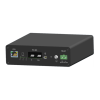
Details the contents of the AMS01 reader package and its external labels.
Explains the 24VDC power input connector and its polarity requirements.
Describes the 4-pin connector for the environmental sensor and its pinout.
Details the RF antenna connectors (A and B) and their designation.
Explains the RS485 connector for Modbus communication and its pin assignments.
Describes the relay output connector for alarm activation.
Details LED indications during Device Firmware Upgrade (DFU) mode.
Details LED indications during normal operation modes.
Instructions for unpacking the AMS01 reader and its accessories.
Details the procedure and recommendations for mounting the AMS01 reader on a DIN rail.
Provides guidance on the optimal placement of the reader within a switchgear compartment.
Specifies the recommended clearance around the reader for connector access.
Details the power wiring requirements, including connector type and wire gauge.
Specifies wiring recommendations for the relay output connections.
Describes the internal battery used for keeping date and time during power loss.
Provides guidance on shielded cable usage and wiring for RS485 communication.
Explains the need for 120 Ohms termination resistors on the RS485 bus.
Discusses factors affecting RS485 bus data rate, such as cable length and number of readers.
Provides a rule for calculating maximum RS485 bus length based on baud rate.
Offers recommendations on baud rate adjustments based on the number of readers on the RS485 bus.
Lists the default Modbus-RTU communication settings for the AMS01 reader.
Details Ethernet cable recommendations and IP address configuration for the AMS01 reader.
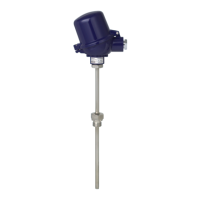
Notes that this manual does not cover specific SAW temperature sensor installation details.
Explains that system configuration is done via Ethernet using the 'AMS01 Configuration Tool'.
Describes how to reset the device and enter Device Firmware Upgrade (DFU) mode.
Details the procedure to reset the AMS01 reader, noting that Ethernet settings are lost.
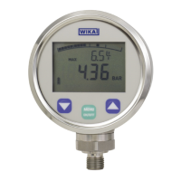
Lists and describes the Modbus registers for input data, including SAW temperature and environmental sensor readings.
Lists the various certifications and standards the AMS01 reader adheres to.
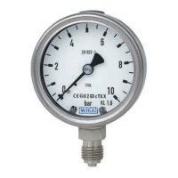
| Accuracy (Pressure) | ±0.5 %FS |
|---|---|
| Protection Class | IP67 |
| Measurement Range (Temperature) | -40 to 85 °C |
| Measurement Range (Pressure) | 0 to 10 bar |
| Measurement Range (Humidity) | 0 to 100 %RH |
| Accuracy (Temperature) | ±0.5 °C |
| Output Signal | 4-20 mA |
| Electrical Connection | M12 connector |
| Wetted Parts Material | Stainless steel |
| Operating Temperature | -40 to 85 °C |