39WIKA operating instructions pressure transmitter, model IS-3
MM/YYYY country code based on 14095850.02 12/2014 EN/CN
EN
4. WARNING!
For ignition protection Ex nA and Ex tc:
Do not separate when energized.
Making the electrical connection
The electrical mounting of the eld case and the angle connector is described in detail below.
■
Ground the cable shield at one end, preferably in the non-Ex area (EN 60079-14).
■
For pressure transmitters with cable output, the shield is usually connected to the case. The simultaneous
connection of the case and the cable shield to ground is only permitted if any accidental energisation between
the shield connection (e.g. at the isolated barrier) and the case can be excluded (see EN 60079-14).
If with pressure transmitters with cable outputs the shield is not connected to the case, the remarks “Shield not
connected to the case” is on the product label. In this case as well the case has to be grounded via the process
connection as the shield has to be grounded.
■
Ensure that no moisture can enter at the cable end of pressure transmitters with cable outlet.
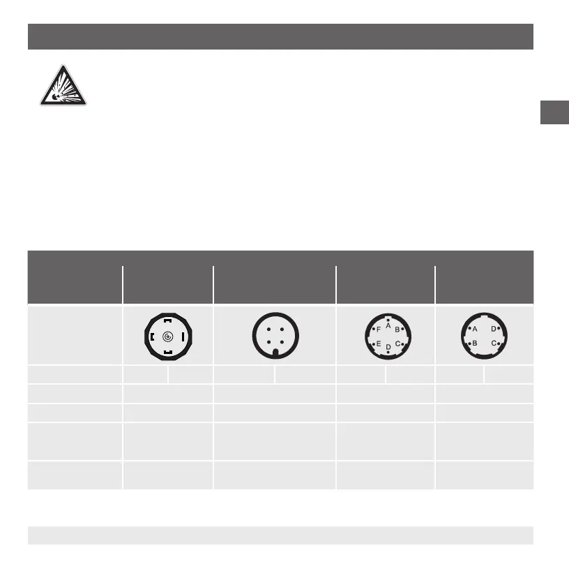
Specicationsoftheelectricalconnections
Angular connector acc.
to DIN 175301-803 A
Circular connector M12 x 1 acc.
to IEC 61076-2-101 A-COD
(4-pin)
Bayonet connector acc.
to MIL-DTL-26482 (6-pin)
Bayonet connector acc.
to MIL-DTL-26482 (4-pin)
Connection diagram
Assignment (2-wire) U
+
= 1 U
-
= 2 U
+
= 1 U
-
= 3 U
+
= A U
-
= B U
+
= A U
-
= B
Cable shield
Wire cross-section max. 1.5 mm²
Cable diameter 6 ... 8 mm
Ship approval:
10 ... 14 mm
Ingress protection per
IEC 60529
IP 65 IP 67 IP 67 IP 67
The stated ingress protection only applies when plugged in using mating connectors that have the appropriate ingress
protection.
1
2
3
4
3
1
2
6. Commissioning, operation
 Loading...