WIKA operating instructions RTD and TC, intrinsically safe designs
3345267.08 06/2011 GB/D
33
GB
9.1 Calculation example for RTD measuring point with thermowell
Use at the partition wall to Zone 0: Calculate the maximum permissible temperature T
max
at the
thermowell tip for the following combination:
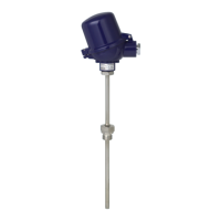
RTD measuring insert Ø 6 mm with built-in model T32.1S head-mounted transmitter, tted into
a Design 3F multi-part thermowell . Power supply is, for example, via a Model KFD2-STC4-EX1
transducer power supply (WIKA Article No. 2341268).
T
max
is obtained by adding the temperature of the medium and the self-heating. The self-heating
of the thermowell tip depends on the supplied power P
o
of the transmitter and the thermal
resistance R
th
.
The following formula is used for the calculation: T
max
= P
o
x R
th
+ T
M
T
max
= Surface temperature (max. temperature at the thermowell tip)
P
o
= from transmitter data sheet
R
th
= Thermal resistance [K/W]
T
M
= Temperature of the medium
Prerequisite is an ambient temperature T
amb
of -20 ... +40 °C.
Example
Resistance thermometer RTD
Diameter: 6 mm
Temperature of the medium T
M
= 150 °C
Supplied power: P
o
= 15.2 mW
Temperature Class T3 (200 °C) must not be exceeded
Thermal resistance [R
th
in K/W] from table = 37 K/W
Self-heating: 0.0152 W x 37 K/W = 0.56 K
T
max
= T
M
+ self-heating: 150 °C + 0.56 °C = 150.56 °C
The result shows that in this case self-heating at the thermowell tip is negligible. As safety
clearance for type-examined instruments (for T6 to T3), another 5 °C must be subtracted from the
200 °C; hence 195 °C would be permissible. This means that in this case temperature class T3 is
not exceeded.
Additional information
Temperature class for T3 = 200 °C
Safety clearance for type-examined instruments (T6 to T3)
*1
= 5 K
Safety clearance for type-examined instruments (T1 to T2)
*1
= 10 K
*1 EN/IEC 60 079-0: 2009 Section 26.5.1
9. Calculation examples for self-heating at the sensor/thermowell tip
 Loading...