3345267.08 06/2011 GB/D
34 WIKA operating instructions RTD and TC, intrinsically safe designs
GB
Simplied verication of intrinsic safety for the above-mentioned combination
Measuring insert Head transmitter Power supply
U
i
: DC 30 V U
o
: DC 6.5 V U
i
: DC 30 V U
o
: DC 25.4 V
I
i
: 550 mA I
o
: 9.3 mA I
i
: 130 mA I
o
: 88.2 mA
P
i
(
max
) at the sensor: 1.5 W P
o
: 15.2 mW P
i
: 800 mW P
o
: 560 mW
C
i
: negligible C
o
: 24 µF C
i
: 7.8 nF C
o
: 93 nF
L
i
: negligible L
o
: 365 mH L
i
: 100 µH L
o
: 2.7 mH
Upon comparing the values, it is obvious that it is permissible to connect these units to one
another. However, the operator must also take into account the values for inductance and
capacitance of the electrical connection leads.
9.2 Calculation example for a sheathed cable with RTD sensor
Use at the partition wall to Zone 0: Calculate the maximum permissible temperature Tmax at the
probe tip for the following combination:
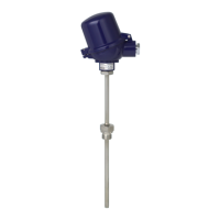
Resistance thermometer without thermowell (TR10-H) Ø 6 mm without transmitter, mounted by
means of a compression tting with stainless steel sealing ring. Power supply is, for example, via
a model Z954 Zener barrier (WIKA Article No. 3247938), for example.
T
max
is obtained by adding the temperature of the medium and the self-heating. The self-heating
of the thermowell tip depends on the supplied power P
o
of the Zener barrier and the thermal
resistance R
th
.
The following formula is used for the calculation: T
max
= P
o
x R
th
+ T
M
T
max
=
Surface temperature (max. temperature at the probe tip)
P
o
= from the Zener barrier data sheet
R
th
= Thermal resistance [K/W]
T
M
= Temperature of the medium
Prerequisite is an ambient temperature T
amb
of -20 ... +40 °C.
Example
Resistance thermometer RTD
Diameter: 6 mm
Temperature of the medium T
M
= 150 °C
Supplied power: P
o
= 1150 mW
Temperature class T3 (200 °C) must not be exceeded
Thermal resistance [Rth in K/W] from table = 75 K/W
Self-heating: 1.15 W x 75 K/W = 86.25 K
T
max
= T
M
+ self-heating: 150 °C + 86.25 °C = 236.25 °C
The result shows, in this case, substantial self-heating at the probe tip.
As safety margin for type-examined instrument (for T6 to T3), an additional 5 °C must be
subtracted from the 200 °C; hence 195 °C would be permissible. This means that in this case
temperature class T3 is exceeded signicantly and therefore not permissible. An additional
thermowell could be used as a remedy.
9. Calculation examples for self-heating at the sensor/thermowell tip
 Loading...