Installation
All piping must comply with local codes and ordinances or with
the National Fuel Gas Code (ANSI Z223.1 NFPA No. 54),
whichever applies. (In Canada: CAN/C.G.A B149). Refer to
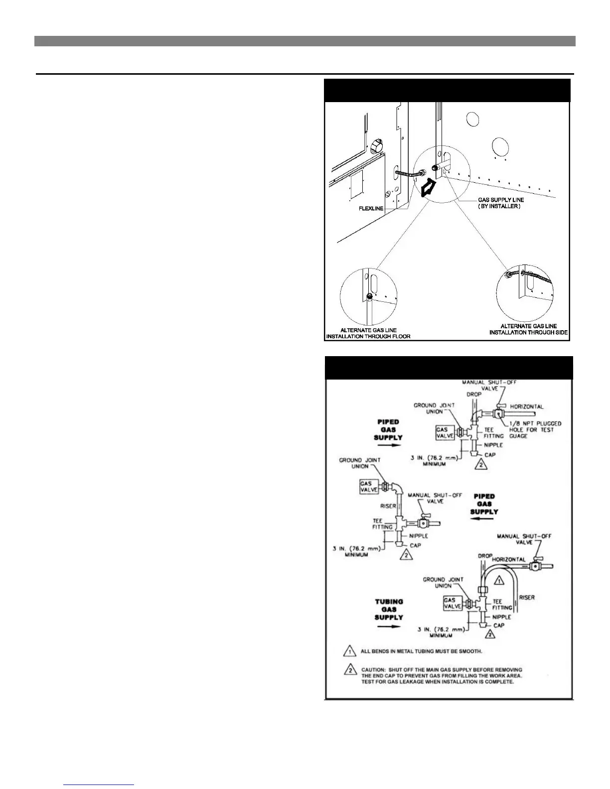
Figure 14 for the general layout of the unit. It shows the basic
fittings needed.
1. Use new, properly reamed pipe free from chips such as
steel or black iron pipe and fittings that are approved by
local codes. Metal chips and debris can damage the gas
valve.
2. Do not thread the pipe too far. Distortion or malfunction may
result from excess pipe within the control valve. Apply a
moderate amount of good quality dope to the pipe threads
only. Leave the two end threads bare. (Figure 28). On L.P.
gas installations, use a compound resistant to action of
liquefied petroleum gases.
3. Use ground joint unions.
4. Install a drip leg (sediment trap) to trap dirt and moisture
before it can enter the gas valve. The nipple must be a
minimum of 3-inches long.
5. Install a manual shutoff valve.
6. Provide a 1/8" NPT test gauge connection immediately
7. Before the gas supply connection to the furnace.
Gas Connection
If installation is for L.P. gas, use a two-stage regulator and
make all connections from the storage the tank to furnace.
Use two pipe wrenches when making the connection to the
valve to prevent turning and/or damage to the gas valve.
The connection between the shutoff valve and the burner
control assembly can be made with an A.G.A / C.G.A. design
certified flexible connector if allowed by local codes.
Tighten all joints securely.
FIGURE 27
FIGURE 26