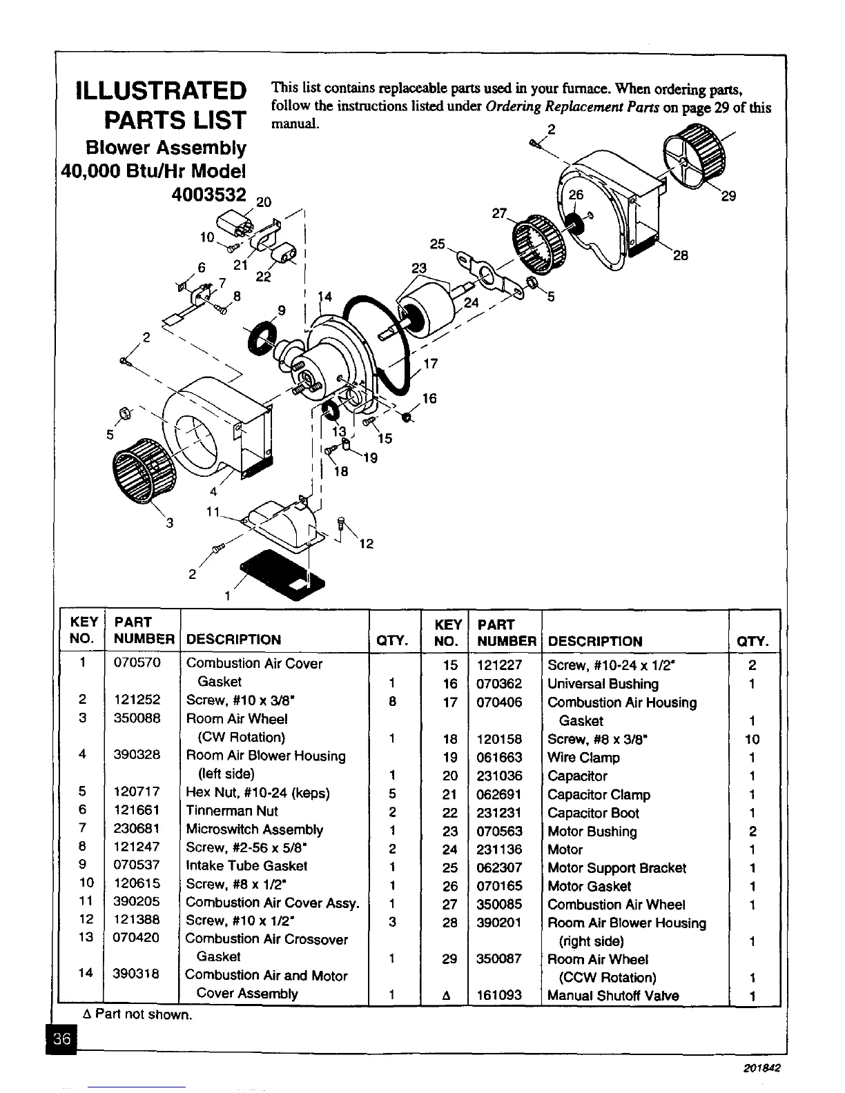
ILLUSTRATE D _is list contains replaceable partsused in your furnace. When ordering pm-ts,
P* A r_,,Pe,_ sa e_,,r follow the instructions listed under Ordering Replacement Parts on page 29 of this
1"/4, M/0 I,,,IO/ manual. 2
Blower Assembly V__ _ _/
40,000 Btu/Hr Model _--_. "_',_
4003532 20 126 "_'_"-'_'J -- "29
6 21 ^F/ 23 '<._"_x/ _ x._
7 _'z I
'°
" 12
KEY! PART
NO. NUMBER
1 070570
2 121252
3 350088
4 390328
5 120717
6 121661
7 230681
8 121247
9 070537
10 120615
11 390205
12 121388
13 070420
14 390318
DESCRIPTION QTY.
KEY PART
NO. NUMBER
Combustion Air Cover 15 121227
Gasket 1 16 070362
Screw, #10 x 3/8" 8 17 070406
Room Air Wheel
(CW Rotation) 1 18 120158
Room Air Blower Housing 19 061663
(left side) 1 20 231036
Hex Nut, #10-24 (keps) 5 21 062691
Tinnerman Nut 2 22 231231
Microswitch Assembly 1 23 070563
Screw, #2-56 x 5/8" 2 24 231136
Intake Tube Gasket 1 25 062307
Screw, #8 x 1/2" 1 26 070165
Combustion Air Cover Assy. 1 27 350085
Screw, #10 x 1/2" 3 28 390201
Combustion Air Crossover
Gasket 1 29 350087
Combustion Air and Motor
Cover Assembly 1 A 161093
DESCRIPTION QTY.
Screw, #10-24 x 1/2" 2
Universal Bushing 1
Combustion Air Housing
Gasket 1
Screw, #8 x 318" 10
Wire Clamp 1
Capacitor 1
Capacitor Clamp 1
Capacitor Boot 1
Motor Bushing 2
Motor 1
Motor Support Bracket 1
Motor Gasket 1
Combustion Air Wheel 1
Room Air Blower Housing
(right side) 1
Room Air Wheel
(CCW Rotation) 1
Manual Shutoff Valve 1
A Part not shown.
2O1842