1400-114
WILLYS MODEL "MB" %-TON
4
x
4
GOVERNMENT TRUCK
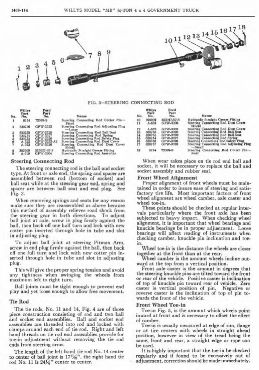
FIG. 3-STEERING CONNECTING ROD
Wilbi
Ford
WIIIJ.
Pd
Part
.Part
Part
Pirt
No.
No.
No.
Nam
No.
No.
No.
Name
1
6134
72089-S
Steering
CanneeUng
Rod
Cottcr
Pi-
10
392900
m7-S-8
Hydnulic
Stral~ht
Gmu
Fitlinc
Front
l1
A-GW
GPW-3336
Steering
Conneetlng
Rod
Duit
Com
a
6307M1
GPW-3323
Stecring
Connstlne
Rod
Adlusting
Plug
Shicld
-Large
12
A-1322
GPW-3332
Stcering
Conneetlnc
Rod
Duit
Conr
8
830755
GPW-3320
Steering
Connedlng
Rad
Bil1
Sept
13
630755
.
GPW-3320
Stecring
Conneetlng Rad
Bal1
%L
1
R30754
GPW-3327
Stecrin~ Conneming
Rod
Sprln~
14
630765
GPW-3320
Steering
Connecllng
Rod
Ball
Ceal
6
610753
GPW-3326
Stecring
Connecting
Rod
Safety
PIUI
16
G30754
GPW-3327
Steering
Connectinn
Rod
Spring
6
A-G22
GPW-3332-A2
Steering
Connming
Rod
Duat
Cover
16
630763
GPW-3326'
Stecrinp
Conneclin~
Rod
Mely
Plw
7
A-G21
GPW-3336
Steering
Connecting
Rod
Dust Cover
17
630767
GPW-3328
Steering
Connecling
Rod
Adjusting
Phs
Sliicid
-Smal1
8
392809
353027-S76
Hydraiilic
Straight
Grnaie
Fitting
18
5134
72OX9-S
Steering
Cannains
Rod
Cottcr
Pln-
O
A419
GPW-3304
Stwring
Connecting
Rod
Asscmbiy
Rear
Steering Connecting Rod
When
wear takes place on tie rod end bal1 and
socket,
it wil1 be necessary to replace the bal1 and
The
steering connecting rod is the ball and socket
assembly
and
rubber
seal.
type. At front or axle end, the spring and spacer are
assembled
between rod (bottom of socket) and
Front
Wheel Alignment
bal1 seat while at the steering gear end, spring and
,
Proper alignment of front wheels must be main-
spacer are between bal1 seat and end plug.
See
tained in order to insure ease of steering and satis-
Fig.
3.
factory tire life. Most important factors of front
wheel alignment are
wheel camber, axle caster and
When removing springs and seats
lor any reason
wheel toe-in,
make sure they are reassernbled as above because
These points should be checked at
regular inter-
this method of assembly relieves
raad
shock from
vals
particularly
where
the
front
axle
been
the steering gear in both directions. To adjust
subjected
t.
heavy
impact.
When
checking
bal1 joint at axle, screw
in
plug firmly against the
alignment,
it
is
important
that
and
ball, then back off one half turn and lock with new
knuckle
hearings
be
in
proper
adjustment.
Loose
cotter pin inserted through hole in tube and slot
hearings
will
affect
of
when
in adjusting plug.
checkiiig camber, knuckle pin inclination and toe-
To adjust bal1 joint at steering Pitman Arm,
in.
screw in end plug
firmly against the ball, then back
Wheel toe-in is the
distance the wheels
are
closer
off one full turn and lock with new cotter pin in-
together
at
the front than
at
the rear.
serted through hole in tube and slot in adjusting
Wheel camber is the amonnt wheels
incline out-
plug.
ward at the top from a vertical position.
Tliis wil1 give the proper spring tension and avoid
Front
axle caster is the amount in degreea that
any tightness
swinging the wheels
from
the steering knuckle pins are tiited toward the front
maximum
left to right turn.
or
rear of the vehicle. Positive caster is inclination
of top of knuckle pin toward
rear of vehicle. Zero
Ball joints must be tight enough to
prevent end
c,ter
is vertical position
of
pin. ~~~~~i~~
or
PI~Y
and Yet loose enough
t0
allow free movement.
revene caster is the inclination
of
top of pin to.
wards the front of the vehicle.
Tie
Rod
Front
Wheel
Toe-in
The tie rods, No.
11
and
14,
Fig.
4
are of three
Toe-in Fig.
5.
is the amount which wheels point
piece construction consisting
of rod and
tW0
bal1
inward
at
front
and is necessary t0
offset
the effect
and socket end assemblies. Ball and socket end
of
assemblies are threaded into rod and locked with
Toe-in is usually measured at edge of
rim,
flange
clamps around each end of tie rod. Right and left
or at tire centen nrith wheels in straight ahead
hand threads on tie rod end assemblies provide for
position, however in view
of
the trad being the
toe-in adjustment without removing the tie rod
came, front and rear,
a
straight edge or rope can
ends from steering arrns.
be used.
The length of the
left hand tie rod No.
14
center
It is highly important that the toe-in be
checked
to center of bal1 joint is
17Iwt,
the right hand tie
regularly and if found
t0
be
exces si vel^
out of
rod No.
11
is
24%"
center to center.
..
adjustment,correctionshouldbemadeimrnediately.


 To Next Page