0200-40
WII.LYS
AIODEL
"MD"
%-TON
4
x
4
GOVERNhlENT
TI<UCK
Next asseiiible tlie bel1 Iiousing to tlie erigiiie.
The clutcli release bearing No.
O.
Fig.
2
is
pre-
luhricatecl and tlie Iiibricant lasts the life of the
bearing.
If tlie bearing is rough, a new bearing
sliould be installed.
Make sure tliat tlie clutch relcase bearing carrier
return spring No.
7,
Fig.
2
is hooked into place. For
tlie
balance of the assemhly, reverse the operations
that
were used in the disassenibly. referring to in-
structions given under "'l'ransmission." Finally
adjust the clutch release cnhle so tliere
is
%>'
free
pedal travel before relcasc Licaring contacts tlie
fingers.
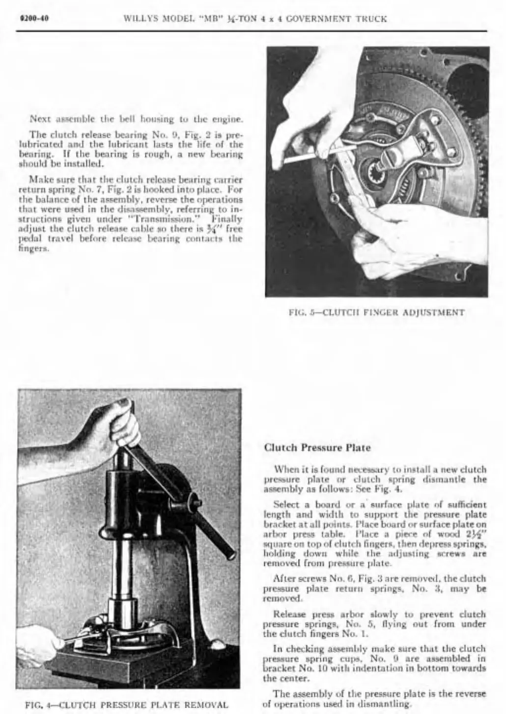
FIG.
4-CLUTCH
PRESSURE
PL,\1'E
REAIOVAL
Clutch Pressure Plate
When it
is
fouiid necessary to iiistall a new clutch
pressure plate or clutch spring dismantle the
assenibly as follows: See Fig.
4.
Select
a
board or a' surface plate
of
sufficient
length and wi<ltli to support tlie pressure plate
bracket at
al1
poiiits. Place board or siirface plate on
arbor
press table. I'lace a piece of wood
2W
square on top of clutch fingers. tlien depress springs.
holding down wliile tlie adjustilig screws are
removed from pressiire plate.
After screws No.
R,
Fig.
3
are removecl, the clutch
pressure plate returii spriiigs. No.
R,
may be
rernoved.
Release press arbor slowly to prevent clutch
pressure springs. No.
5,
flying out frorn under
the clutch
fingers No.
1.
In checking assembly make sure that tlie clutch
pressure spring clips, No.
O
are assenibled in
bracket No.
10
witli indentation in bottorn towards
the center.
Tlie
assembly of tlie pressiire plate is the reverse
of operations used in dismantling.