WILLYS MODEL "MB" %-TON
4
x
4
GOVERNMENT TRUCK
0800-81
No.
1
a
B
4
6
6
FïC.
&TRANSFER
CASE
EXPLODED
VIEW
Wlllfi
Fad
Psit
No.
A-963
A-Q6a
A-992
628R3
61575
A-957
Part
No.
r&smx+
GP-7711
GP-7702
OIY-l2ll2
GP-7723
GPW-7773
Name
Shlft
Fort
to
Rod
Sn
Sarr
Front
WheI
Drlve
Shlft
Fnrk
Output
Shafl
Cliiuh
Gcar
Outpul
SIinIt
BCarln~
Ciip
Olit~ul
Sliaft
Hrarinq
Canr
end
Wleri
Oiitpul
Sliall
Beuring
Cap
Gasket-
Disassembly
of
Front
Cap Assembly
1.
Remove cotter pin, No. 28, nut, No. 29 and
washer No. 27.
2.
Remove universal joint yoke No. 26.
3.
Remove oil seal No. 30.
4.
Remove set screw No. 1 and shifting rod No.
8.
5.
Clutch gear No.
3
and fork No. 2 can now be
rernoved together.
6.
Remove output clutch shaft No. 12 carefully
pressing through the bearing No. 10.
7.
Remove snap ring No.
13.
8.
Remove bearing No. 10.
Disassembly of
Rear
Cap
Assembly
1.
Remove cotter pin No. 31, nut, No. 32, and
washer No. 36.
2.
Rernove cornpanion flange No.
33.
3.
Remove oil seal No.
42.
4.
Remove speedometer driven gear, No. 45.
5.
Output shaft No. 67 can now be removed from
cap
No. 43 after which bearing cone No. 51
and the speedometer driving
gear No. 40 can
be pressed off the shaft.
Shims No. 41 provided between the rear
cap
No.
43
and case
No.
34 are for adjustment of the
roller bearings No. 51 and 5. Bearings should be
adjusted so that there is not more than .003" end
movement of the shaft No.
67.
Reassernbling is merely
a
reversal of the fore-
going. When assembling the transfer case to the
transmission be sure that the
countenhaft lock
plate No: 41, Fig. 4, Transmission Section is
properly located
between the two siiafts and fits
into transfer case. Make certain that
al1 parts are
carefully washed and free from
al1 dirt and foreign
matter.
Assembly
of
Transmission and Transfer Case
to
Vehicle
The installation of the assembly to the engine is
the
reversal in the operations for disassembly as
covered under heading
"Removal of Transrnission
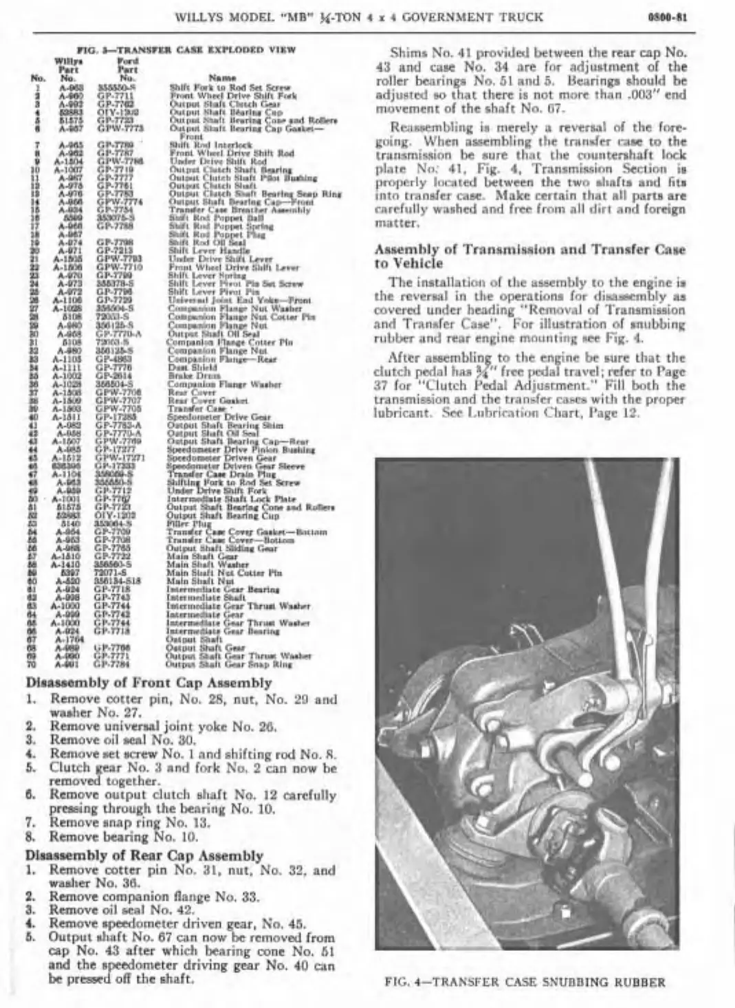
and Transfer Case". For illustration of snubbing
rubber and
rear engine rnounting see Fig.
4.
Aftër assernbling to the engine be sure that the
clutch pedal has
x"
free pedal travel; refer to Page
37
for "Clutch Pedal Adjuctment." Fill both the
transmission and the transfer cases with the proper
lubricant. See 1-iihrication Chart, Page 12.
FIG.
4-TRANSFER CASE SNUBBING RUBBER