1000-90
WILLYS MODEL "MB" %-TON
4
x
4
GOVERNMENT TRUCK
4.
Install brake tube and bolt backing plate in
position.
5.
Grease wheel bearings and assemble bearings,
wheel hub and drum on
the wheel bearing
spindle. Install
wlieel bearing washer, No. 19,
Fig.
2,
and adjusting nut, No. 20. Tighten nut
until there is a slight drag on the bearings, when
the wheel is turned, then backoff approximately
one-quarter turn. Install lock
waslier No. 21
and nut No.
22,
tightening nut into place and
then
bendina the lock washer over on the
-
loek
nut.
6.
With Bendix joint install axle drive Bange on
axle
splines, without shims.
Measure the space with a Feeler Gauge between
the outer end of the wheel hub and the inner
face of the drive
flange, Fig. 10. This wil1 de-
termine the amount of shims to be installed. In
order to have proper clearance in the universal
joint, it is
necessary to add a .040f1 shim to those
required as measured by tlie Feeler Gauge.
Remove driving hub and install the correct
amount of
sliims replacing driving hub on spline
shaft and install six cap screws.
With Rzeppa joint be sure to install
al1 the
shims as removed when dismantling the axle drive
Bange.
(.060" shims in each side).
7.
Assemble axle shaft washer, nut and cotter pin.
8.
Install the Hub Cap.
9.
Assemble Wheel.
10. Check front
wlieel alignment, which is covered
uiider "Steering".
11.
Bleed Brake.
Make certain the
steering knuckle universal
joint is lubricated through the
filler plug in the
knuckle
housing. See Lubrication Chart, Page 12.
FIG. 10-CHECKING FLANGE END PLAY
Replacing
Steering
Knuckle
Bearing
Re'placement of the bearings or bearing cups on
the king pins
necessitates removal of the hub and
brake drum assembly, wheel bearings, axle shaft,
wheel bearing spindle and the
steering knuckle.
The
steering kniickle sliould be disassembled as
follows:
1.
Remove the eight screws No. 33, Fig.
2
which
hold the oil seal retainers in place No. 34 and
38..
2.
Remove the four nuts holding the lower king
pin bearing cap, No.
41.
3.
Remove the four nuts, No.
3
holding the upper
steering arm in place, and remove brake hose
shield
also arm No.
5.
The steering knuckle No.
8
can now be removed from the axle.
4.
Wash al1 parts in cleaning solution and inspect
bearings and races for scores, cracks or chips.
All daniaged parts should,of course, be replaced.
In the event the bearing cups are damaged, they
can be removed by the use of a driver or a
suitable drift.
Reassembling
Steering
Knuckle
Reverse the procedure outlined above to re-
assemble the unit. When reinstalling the steering
knuckle, sufficient shims must be installed under
the arm and lower bearing cap
so the proper
tension
wil1 be maintained on the bearinrr. The
shims are available in
thicknesses of .003"T .00511,
,010" and .030".
Install one each of tlie .003", .005", .OIO1' and
.0301' shims over studs on the steering knuckle,
top and
bottom. Install the arm, and lower bear-
ing cap, lock washers, and nuts, and tighten
securely. Check the tension of the bearings by
hooking checking scale in the hole in tlie arm at
tie rod and socket, either
remove or add shims until
the load is approximately
25
to 35 inch pounds,
without. oil seal assembly in position. Make sure
there are the
Same thickness of Shims between arm
and knuckle as
between lower cap and knuckle.
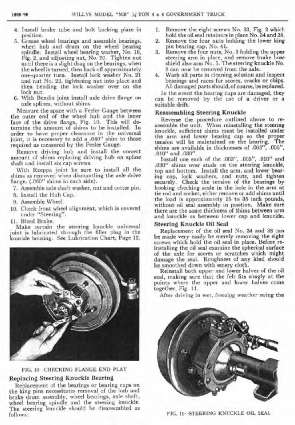
Steering
Knuckle
Oil
Seal
Replacement of the oil seal No. 34 and 38 can
be made very easily be merely removing the eight
screws which hold the
oil seal in place. Before re-
installing the oil seal examine the spherical surface
of the axle for scores or scratches which might
damage the seal. Roughnecs of any kind should
be smoothed down with
emery cloth.
Reinstall both upper and lower halves of the oil
seal, making sure that the felt fits snugly at the
points
wliere the upper and lower halves come
together, Fig.
11.
After driving in wet, freezipg weather swing the
FIG. 11-STEERING ICNUCKLE OIL SEAL