Do you have a question about the Wilo Comfort Series and is the answer not in the manual?
Considerations for pump set placement including ventilation, frost, drainage, security, and access.
Requirements for stable foundations and pipework connections, emphasizing size and cleanliness.
Ensuring water is free from impurities and detailing water connection procedures and safety aspects.
Checks for supply compatibility, cable ratings, and earth bonding in accordance with regulations.
How Wilo pressurisation units control pressure via transducer and controller.
Overview of factory settings for pressure, alarms, system fill, and pump configuration.
Description of Auto Restart, Low Water, Low Pressure, and High Pressure alarms.
Details on Excess Starts, Pump Trip, and Pump Fail alarms with their causes and actions.
Functionality of System Fill for initial setup and automatic Pump Check for inactive units.
Configuration of Alarm Latching, Alarm Log, and Volt Free Contacts for remote monitoring.
Ensuring correct piping, wiring, earthing, and system filling before commissioning.
Step-by-step guide to calculating CF pressure, setting air pressure, and starting the unit.
Scheduled checks for leaks, corrosion, valve operation, and shaft rotation every 6 and 12 months.
Legal requirements for inspecting accumulator vessels as pressure systems under HSE regulations.
Terms of the 12-month warranty, inspection rights, and consequences of unauthorized modifications.
Required information for service team when requesting a site visit.
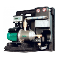
This document provides installation, operation, and maintenance instructions for the Wilo Comfort Series Pressurisation Units, specifically models P135, P235, P160, P260, P180, and P280. The information is dated 07/01/2013.
Location When selecting a location for the pump set, ensure the area is dry, well-ventilated, and protected from frost. Adequate drainage facilities should be available. The area must be secure to prevent unauthorized access or tampering. Provision for lifting equipment should be made. A minimum clear area of 1 meter in front of the panel and 0.5 meters at either side and rear is required for maintenance access.
Foundations Foundations must be rigid and level. While a plinth is not essential, it can help keep the set clear of damp. When fixing the unit, take care not to distort the set by tightening unevenly.
Pipework Pipework connections to the set should be at least the same size as the connections on the unit. If smaller connections are required, contact Wilo for advice.
Impurities The water used should be clean and free from impurities. The sand content should not exceed 0.01g/l, and any suspended bodies should be small enough to avoid clogging or wearing the hydraulic components. For applications involving dirty water, a filter must be installed in the suction pipe.
Electrical Connections The installer must verify that the available electricity supply is compatible with the voltage and frequency specified on the CE Label. Cables and fuses for the incoming electricity supply must be rated to handle all pumps running simultaneously. Earth bonding, in line with current IEE regulations, is the responsibility of the installer.
Water Connections A wholesome water supply can be connected directly to the float valve. Back contamination is prevented by the AB airgap within the pressurisation unit, allowing connection to systems up to and including category 5. A quick fill loop bypassing the pressurisation unit is not necessary, as the comfort controller includes a system fill feature that allows the unit to fill the system via the AB air gap over a 24-hour period.
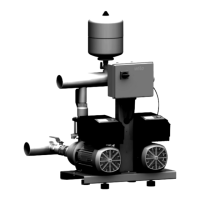
Wilo Pressurisation units are available in both 1-pump and 2-pump (Duty/Standby) configurations.
General Wilo Pressurisation units operate on a closed-loop pressure control system, utilizing a transducer and an electronic controller. The control philosophy ensures the duty pump runs to maintain the Cold Fill Pressure (CF) constantly. In two-pump systems, the duty pump rotates between both pumps after each cycle to ensure even wear. If the duty pump fails, the standby pump automatically starts.
Factory Settings:
These values can be viewed in VIEW mode by pressing the down arrow and scrolling through the menu. Pump configuration can be changed between Hand-Off-Auto in this mode. These values can be altered in USER mode to suit specific site conditions by entering the password "1234" and following the provided flow diagram.
Auto Restart The unit will automatically restart after a mains failure or power down. The BMS volt-free contact 8 can be configured to signal a mains failure if required.
Low Water If the water level in the break tank drops to an unacceptably low level, the float switch activates, preventing the pumps from running and triggering an audible, visual, and volt-free alarm. If alarm latching is OFF, the alarm will reset once the break tank has been replenished with water.
Low Pressure (LP) This parameter can be adjusted in the User menu. If the system pressure falls below the LP setting, an audible, visual, and volt-free alarm activates. If alarm latching is OFF, the alarm will reset once the duty pump has increased the pressure past the LP setting.
High Pressure (HP) This parameter can be adjusted in the User menu. If the system pressure rises above the HP setting, the pump stops, and an audible, visual, and volt-free alarm activates. This parameter can be changed by following the flow diagram. If alarm latching is OFF, the alarm will reset once the system pressure has fallen below the HP setting.
Excess Starts (ES) If ON, this alarm will activate and stop the pumps if a pump has started too many times within a set period. This will trigger an audible, visual, and volt-free alarm. The excess starts variables can be adjusted during commissioning.
System Fill (SF) If ON, this feature overrides the System Leak alarm and allows the pump to run for 24 hours or until the CF pressure has been met. After this, the controller returns to normal operation. This feature is intended for initial system filling during commissioning.
Pump Trip The FLC (Full Load Current) of the pump is monitored by the controller while running. If exceeded, the pump will stop, and an audible, visual, and volt-free alarm will activate. On a 1-pump unit, or if both pumps are stopped via a trip alarm, the boiler interlock volt-free alarm is also activated.
Pump Fail The FLC of the pump is monitored by the controller while running. If no current is drawn, the pump will stop, and an audible, visual, and volt-free alarm will activate. On a 1-pump unit, or if both pumps are stopped via a fail alarm, the boiler interlock volt-free alarm is also activated.
Pump Check All Wilo pressurisation units automatically check pump operation by running them for a short period if they have been inactive for a long time. The pump check variables can be adjusted during commissioning.
Alarm Latching If OFF, all alarms will reset once the alarm condition deactivates. If ON, alarms must be manually reset via the reset button on the front panel.
Alarm Log The alarm log records the last 30 alarm events, which can be viewed from the view or user mode.
Volt-free contacts This unit provides 10 volt-free alarms for remote monitoring. All contacts are rated at 230V 5 Amp max.
The unit also has one volt-free contact rated for 230V 10Amp max, which can be programmed during commissioning for:
Before commissioning, ensure the following:
Calculate the Cold Fill Pressure (CF): CF = (A + 2.5) / 10.2 Bar Where A is the height of the building above the pressurisation unit in meters. For Roof Top plant rooms, the minimum CF is 0.8 Bar.
Vessel Air Pressure: Check the air pressure in the vessel when it is empty of water. The air pressure should be equal to the calculated CF pressure. Use nitrogen to increase pressure if necessary.
Initial Setup:
System Settings: Key in password "1234" to enter the Main Menu and scroll through windows to set the installation parameters. Set CF as calculated above. LP should be at least 0.2 bar below CF, and HP should be 0.5 bar below the setting on the system safety valve.
System Fill: If the system has not been filled by a quick fill loop, use the System Fill function by selecting ON. This allows the pump to run for 24 hours or until the CF pressure has been met.
Pump Operation: Switch pump(s) into Auto.
Alarm Testing:
Final Checks: Ensure all settings are returned to normal and all valves are open. Check the units and system pipework for any leaks and flooding.
Warning: When running the unit in System Fill mode, the system leak alarm is switched OFF, and the pump will continue to run even if there is a leak in the system.
Wilo pressurisation units are designed for minimum maintenance. However, routine inspection is necessary and can be carried out by Wilo. Contact their service department for details.
Every 6 months:
Every 12 months:
Warning: Wilo advises that power to the unit be isolated before undertaking any of the above maintenance tasks, as the pump will start automatically.
Accumulator vessels are classified as a pressure system under the Health and Safety Executive 'Pressure system safety regulations 2000'. This regulation imposes a legal requirement on the user/maintainer to have the equipment inspected regularly by a competent company as a mandatory duty under parts 7 & 8 of the regulations. While a supplier/installer may not fall under the category of user/maintainer, they are still obligated to inform the user/maintainer of their legal and mandatory duties under the HSE Regulation.
Wilo recommends that any vessel over 250 bar/litres should undergo a working test every 6 months and a thorough examination every 24 months. Bar/Litre = Maximum Working Pressure (Bar) x Volume of vessel (Litres).
This equipment is covered against manufacturing defects for 12 months from the date of purchase. The warranty covers the replacement of parts or products verified as having a manufacturing defect upon inspection at the factory. WILO reserves the right to inspect an installation to verify that the equipment has been installed in accordance with the written instructions. Any modifications to the supplied equipment must be approved in writing; failure to do so will invalidate the warranty.
Site Visit Before requesting a site visit, the following information must be available to the service team:
This section provides a fault-finding chart to help diagnose and resolve common issues with the pressurisation unit.
| Indication | Possible Reason | Action | | Function Description
| Insulation Class | F |
|---|---|
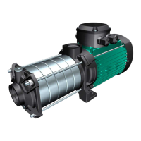
| Application | Heating and cooling systems, domestic hot water circulation |
| Operating Modes | Constant speed, proportional pressure, constant pressure |
| Motor Type | Electronically commutated (EC) motor |
| Control Type | Automatic, electronic |
| Liquid Temperature Range | 110°C |
| Maximum Operating Pressure | 10 bar |
| Power Supply | 230 V, 50/60 Hz |
| Pump Housing Material | Cast iron, stainless steel |
| Max Liquid Temperature | 110°C |
| Impeller Material | stainless steel |
| Type | Circulation Pump |