en
42 Installation and operating instructions • Wilo-Control EC-L • Ed.04/2022-09
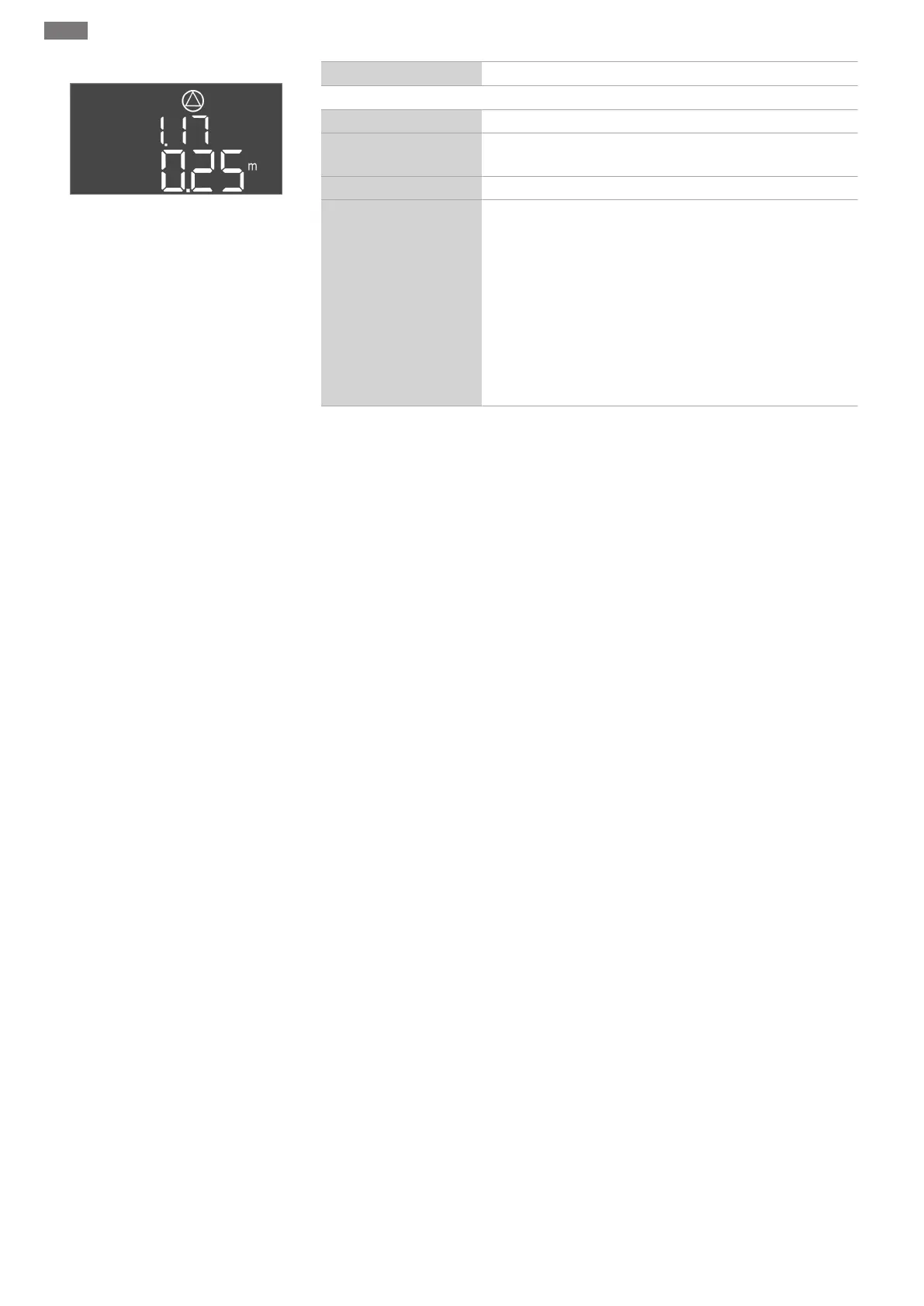
Fig.64: Menu 1.17
Menu no. 1.17
Software version: All
Description Peak-load pump 2 Off level
Value range
0.06...12.5m (NOTICE!The actual value range is dependent
on the setting in menu 5.09.)
Factory setting 0.25m
Explanation
“Drain” operating mode: The value must be 0.03m lower than
the “Peak-load pump 2 On” level (menu 1.16). The switch-off
level must be greater than/equal to the switch-off level of the
peak-load pump (menu 1.15).
“Fill” operating mode: The value must be 0.03m higher than
the “Peak-load pump 2 On” level (menu 1.16). The switch-off
level must be lower than/equal to the switch-off level of the
peak-load pump (menu 1.15).
NOTICE!The menu item is only visible if the value “Level” or
“Bell” have been set in menu 5.07.
8.5.4 Menu 2: ModBus RTU connection
The switchgear is equipped with an RS485 interface for connection via ModBus RTU. Dif-
ferent parameters can be read and also changed to some extent via the interface. In this
case, the switchgear works as a Modbus slave. An overview of individual parameters and a
description of the data types used are shown in the appendix.
 Loading...


