English
Installation and operating instructions Wilo-DrainLift XS-F 29
7.3 Installation
Before starting installation, check the scope of delivery of the unit and the local installation
conditions. .
Fig. 14: Pre-mounting the connections
The inlet and pressure pipes must be pre-mounted as illust-
rated (Fig. 14) in the room where the unit is to be installed. If
the unit is mounted to the right of the toilet, assembly is the
reverse of the illustration.
1 Pressure pipe
2 Ventilation pipe
3 Inlet for wall-hung toilet
4 Inlet pipe for shower/bidet
5 Inlet pipe for washbasin
Fig. 15: Buoyancy protection
The DrainLift XS-F cannot be flooded, which means the
installation site must be secure against flooding. EN 12050-
3 requires that sewage lifting units must be protected
against buoyancy (Fig. 15). Place the unit in the installation
room and align it to the pipes to be connected. Use a long 10
mm stone bit to drill a marking just above the tank (not
above the detachable hood), so that the hanger bolt to be
mounted later will touch or only have a slight gap to the tank.
After drilling, take the unit out of the maintenance hatch and
finish drilling the hole. Then put in the wall plug. Only fit the
hanger bolt after
you have installed the system.
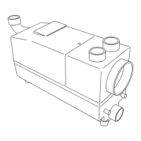
Fig. 16: Preparing the connecting ports of the unit
Open the connecting ports for the drainage fixtures in addi-
tion to the wall-hung toilet (shower, washbasin and / or
bidet) and for the ventilation ports using a 40 mm hole saw
(Fig. 16). Then deburr the holes.
CAUTION! Risk of damage!
Remove the cut-out circle; do not leave it in
the tank.
4 5
~
480
~
275
35
~
235
500
3
1
2
35
180
400
Ø40
 Loading...