English
Installation and operating instructions Wilo-DEA 21
Fig. 8 Manifold pipe support using vibration damper
Fig. 9 Break tank (example)
23 Inlet with float valve (accessories)
24 Air supply/extraction with insect protection
25 Inspection opening
26 Overflow
Ensure adequate drainage. Protect siphon or valve
against ingress of insects. Do not connect directly
to sewer system
(free outlet according to EN 1717)
27 Draining
28 Extractor (connection for DEA)
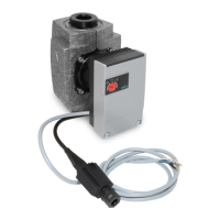
29 Low-water signal generator with terminal box
29a Circuit diagram
bl = blue sw - bl = NC contact
br = brown sw - br = NO contact
sw = black
30 Connection for flushing apparatus, inlet
31 Level display
Fig. 10 Drainage pipe for flushing
33 Drainage pipe
Nominal diameter = pump connection nominal
diameter or a nominal diameter smaller than the
pump connection nominal diameter
Note: If a diaphragm pressure vessel is arranged on the
end pressure side, arrange the drainage directly
downstream of the diaphragm pressure vessel.
 Loading...