English
20 WILO SE 10/2010
Installation and operating instructions Wilo pressure boosting systems (DEA)
Captions:
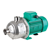
Fig. 1a
Example of a pressure boosting system with MHI
pumps and ER
switchgear
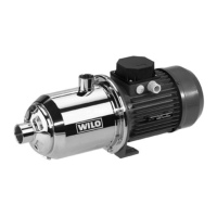
Fig. 1b Example of a pressure boosting system with
MVISE and VR switchgear
Fig. 1c Example of a pressure boosting system with MVI
and CC switchgear (floor model SG)
1Pumps
2 Control equipment
3 Base frame
4 Inlet manifold pipe
5 Pressure manifold pipe
6 Check valve
7 Non-return valve
8 Diaphragm pressure vessel with throughflow
fitting
9 Pressure sensor/pressure gauge
10 Standard bracket
11 Low-water cut-out switchgear (WMS), optional
Fig. 2a Pressure sensor and diaphragm pressure vessel
kit
8 Diaphragm pressure vessel
9 Pressure gauge
12 Pressure sensor
12a Electrical connection, pressure sensor
13 Draining/venting
14 Stop valve
Fig. 2b Throughflow fitting operation/pressure testing
the diaphragm pressure vessel
A Open/close
B Draining
C Check supply pressure
Fig. 3 Information table: nitrogen pressure, diaphragm
pressure vessel (example)
a Nitrogen pressure according to the table
b Start-up pressure, base load pump in bar PE
c Nitrogen pressure in bar PN2
d Nitrogen measurement without water
e Important! Introduce nitrogen only
Fig. 4 Protection against low water level (WMS) kit
13 Draining/venting
14 Stop valve
15 Pressure switch
15a Pressure switch setting
Factory setting:
ON 1.3 bar/OFF 1.0 bar
Clockwise (+), increase switching points
Anti-clockwise (-), reduce switching points
Switching difference (0.3 bar maintained!)
15b Connection in control device
(see terminal diagram)
Fig. 5 Example of direct connection
(hydraulic diagram)
Fig. 6 Example of indirect connection
(hydraulic diagram)
16 Consumer connections upstream of the DEA
17 Diaphragm pressure vessel on the end pressure
side with bypass
18 Consumer connections downstream of DEA
19 Drainage connection for flushing the system
20 DEA with 4 pumps
21 Diaphragm pressure vessel on the inlet side with
by-pass
22 Unpressurised break tank on the inlet side
34 Flushing apparatus for the inlet connection of the
break tank
35 Bypass for revision/maintenance
(not permanently installed)
Fig. 7a Assembly: vibration damper and compensator
A Screw the vibration damper into the threaded
inserts provided and secure with locking nuts
B Compensator with extension limiters (accessories)
C Fixation of pipes downstream of the DEA, e.g. with
pipe clips (onsite)
Fig. 7b Assembly: flexible connection lines
A Floor fixing, structure-borne noise insulation
(onsite)
B Compensator with extension limiters (accessories)
C Fixation of pipes downstream of the DEA, e.g. with
pipe clips (onsite)
D Threaded valves (accessories)
 Loading...